beautypg.com

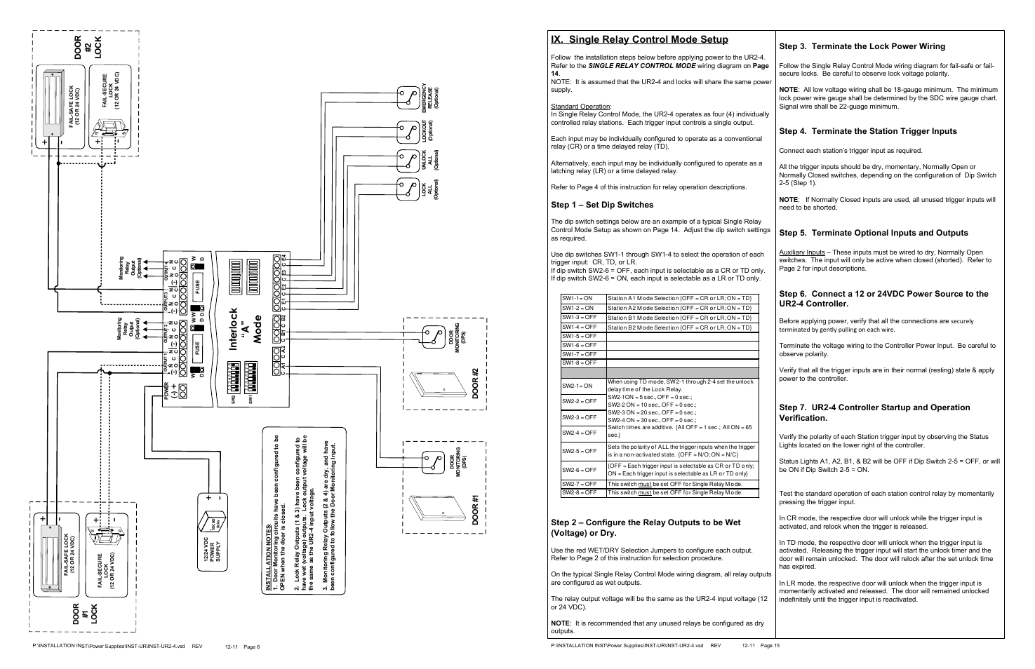
Ix. single relay control mode setup, Do o r # 2 l o c k, Step 1 – set dip switches – SDC UR2-4 User Manual

Page 15: Step 3. terminate the lock power wiring, Step 4. terminate the station trigger inputs, Step 5. terminate optional inputs and outputs, Do o r # 1 l o c k

Ix. single relay control mode setup, Do o r # 2 l o c k, Step 1 – set dip switches | Step 3. terminate the lock power wiring, Step 4. terminate the station trigger inputs, Step 5. terminate optional inputs and outputs, Do o r # 1 l o c k | SDC UR2-4 User Manual | Page 15 / 33 Ix. single relay control mode setup, Do o r # 2 l o c k, Step 1 – set dip switches | Step 3. terminate the lock power wiring, Step 4. terminate the station trigger inputs, Step 5. terminate optional inputs and outputs, Do o r # 1 l o c k | SDC UR2-4 User Manual | Page 15 / 33