This manual is in “booklet” format, Use these bars – Schwank STW-JZ1 User Manual
Page 41
41
STW-JZ / IW I&O Manual
IM101229
RL: 12A- BA
RD: DEC 2010
22. SPARK IGNITION CIRCUIT
The step-up transformer in the ignition control provides spark ignition at 30,000 volts (open cir-
cuit). To check the spark ignition circuit, proceed as follows.
Shut off gas supply to the gas control
Disconnect the ignition cable at the ignition control stud terminal to isolate the circuit from
the Spark Igniter or Igniter / Sensor
Prepare a short jumper lead, using heavily insulated wire such as ignition cable
CAUTION
In the next step, DO NOT allow fingers to touch either the stripped
end of the jumper or the stud terminal. This is a very high voltage circuit and
electrical shock, personal injury, or death can result.
Perform this test immediately upon energizing the system before the Ignition Control goes
into safety lockout and interrupts the spark circuit. Touch one end of the jumper firmly to the
ignition control GND terminal. (DO NOT remove the existing ground lead.) Slowly move the
other end of the jumper wire toward the stud terminal on the Ignition Control to establish a
spark.
Pull the wire away from the stud and note the length of gap at which spark discontinues.
A spark length of 1/8 in. (3 mm) or more indicates satisfactory voltage output. If no arc can
be established, or the maximum spark is less than 1/8 in. (3 mm), and power to the Ignition
Control input terminals was proved, replace the Ignition Control.
TURN OFF THE POWER AND RECONNECT THE IGNITION WIRE TO THE IGNITION CONTROL STUD. DIS-
CONNECT THE IGNITION WIRE FROM THE IGNITER AND REPEAT THE STEPS ABOVE BY GROUNDING
THE WIRE OUT TO THE TUBE BODY THIS TIME. TURN ON THE POWER AND PULL THE WIRE AWAY
FROM THE TUBE AND NOTE THE LENGTH OF GAP AT WHICH THE SPARK DISCONTINUES. IF THERE IS
NO SPARK OR WEAK SPARK REPLACE THE IGNITION WIRE.
USE THE BLACK BARS BELOW AS A GUIDE FOR AD-
JUSTMENT. USE THE BARS THAT COINCIDE WITH
THE FORMAT & SIZE OF THIS PUBLICATION .
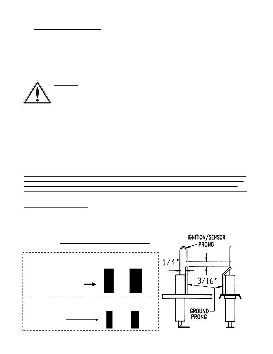
SPARK IGNITER SET UP
Use the following diagram to check the Igniter gap. If the gap is incorrect all adjustments
should be made with the GROUND PRONG/PIN ONLY! DO NOT BEND THE IGNITER
PRONG!!!!
3/16”
1/4”
3/16” 1/4”
IF
this manual is in
“booklet” format
(8.5” x 11” folded in half)
use these bars
IF this manual is 8.5” x 11”
“full page” format
use these bars
OR