Schwank 2-Stage Series User Manual
Page 7
7
SET(U)-F / ITT(U)-F Manual
IM091221
RD: FEB 2014
RL: 8B
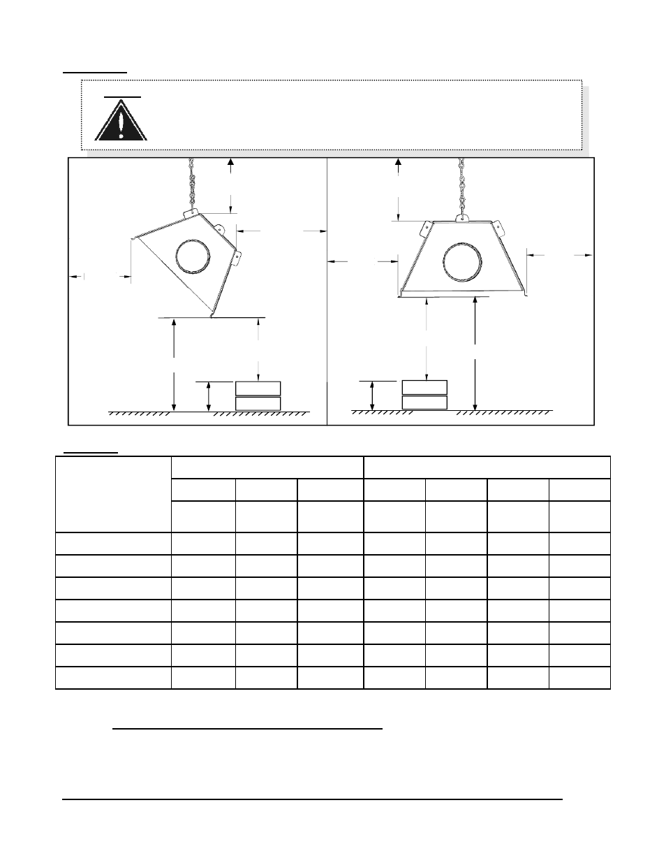
TABLE 1 MINIMUM CLEARANCES TO COMBUSTIBLES*
FIGURE 1 MINIMUM CLEARANCES TO COMBUSTIBLES* - refer to Table 1 for values
*NOTE: Clearances are measured from the reflector.
The clearance to combustible materials represents the minimum distance that must be main-
tained between the heater and a nearby surface. The stated clearance to combustibles
represents a surface temperature of 90F° (50C°) above room temperature.
It is the installer’s responsibility to ensure that building materials with a low heat
NOTE: A ‘PEEL & STICK’ SIGN IS SUPPLIED: USE AN INDELIBLE MARKER TO
ENTER VALUES ‘H’, ‘S’, ‘F’, & ‘B’ ON .
POST THE SIGN ADJACENT TO THE HEATER THERMOSTAT OR IN A
PROMINENT LOCATION.
See next page for details.
F
D
B
A
S
S
C
Suspended at an
angle up to 45°
Suspended
horizontally
C
FLOOR
H
T
H
M a x i m u m
Stack Height
H = T- C
‘T’ is meas-
ured on site,
FLOOR
T
M a x i m u m
Stack Height
H = T- C
‘T’ is meas-
ured on site,
MODEL
SET(U) / ITT(U)
Both “Straight”
& “U-Tube”
HORIZONTAL
ANGLE UP TO 45 DEGREES
TOP
SIDE
BELOW
TOP
REAR
FRONT
BELOW
A
inches (cm
)
S
inches (cm)
C
inches (cm)
D
inches (cm)
B
inches (cm)
F
inches (cm)
C
inches (cm)
200,000/140,000 7” (18) 22” (56) 68” (172) 7” (18)
1” (2.5) 57” (145) 68” (172)
175,000/125,000 6.5” (16.5) 20” (51) 68” (172) 6.5” (16.5) 1” (2.5) 47” (119) 68” (172)
155,000/110,000 6” (15) 19” (48) 64” (163) 6” (15)
1” (2.5) 44” (112) 64” (163)
130,000/90,000
4” (10) 11” (28) 60” (152) 5” (13)
1” (2.5) 35” (89)
56” (142)
110,000/75,000
3” (8)
10” (25) 60” (152) 4.5” (11)
1” (2.5) 26” (66)
54” (137)
100,000/70,000
7” (18) 22” (56) 68” (172) 7” (18)
1” (2.5) 57” (145) 68” (172)
80,000/60,000
2.5” (6)
6” (15) 42” (107) 3.5” (9)
1” (2.5) 23” (59)
38” (97)