Set / itt straight tube system – Schwank 2-Stage Series User Manual
Page 15
15
SET(U)-F / ITT(U)-F Manual
IM091221
RD: FEB 2014
RL: 8B
9.1
SET / ITT STRAIGHT TUBE SYSTEM
~ BURNER AND TUBE INSTALLATION
1) Install Hangers:
i: No closer than 3” (5 CM) and no further than 5” (10 cm) from the burner/tube flange
ii: No closer than 6” (15 cm) either side of a tube connection in the system
iii: No further than 24” (61 cm) either side of a tube connection in the system
2) With all hangers in alignment and suspended at the same height, insert first aluminized tube
section, through 4" hole into first two wire hangers.
NOTE: INSTALL THE FIRST AND SECOND TUBES (FROM BURNER END) WITH THE WELDED SEAM
ALONG THE TUBE LENGTH FACING DOWNWARD
3) Bolt burner to flange on first tube section,
SEE FIGURE 8
.
IMPORTANT NOTE: Models with inputs 100,000, 175,000 & 200,000 refer to section 9.3
4) Slide a Torctite tube coupler over the swaged end of the first tube, then join the second tube
over the swage in the first tube
5) Slide the Torctite coupler into position across the center of the joint -
SEE FIGURE 9
6) IMPORTANT: TOURQUE THE COUPLER BOLTS TO 40 ft-lbs
7) Subsequent lengths of tube can then be installed, by joining them together swaged portion
inside the next tube and locking the joints using the Torctite coupler.
SEE FIGURE 9.
8) If there is a 90° elbow in the system refer to Section 7 and Figures 3 & 4
9 INSTALLATION OF HANGERS, TUBES AND BURNER
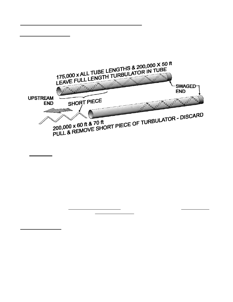
TURBULATOR NOTES:
1. 200,000 x 60 ft & 70 ft: REMOVE SHORT PIECE OF TURBULATOR FROM UP-
STREAM END OF LAST TUBE PRIOR TO INSTALLATION OF TUBE
2. Turbulators are ALWAYS installed at the vent end of the heater.