Figure 3, 24” (61 cm) – Schwank compactSchwank P40-R User Manual
Page 13
13
P40R-F I&O Manual
IM120801
RD: MAY 2014
RL: 3A
6.
PRE INSTALLATION SURVEY
Carefully survey the area to be heated. It is recommended that a full heating design including
heat loss calculation be conducted on the structure or area to be heated. Heater sizing, quan-
tity, and placement must consider available mounting height, sources of greatest heat loss.
The certified clearances to combustibles must always be maintained with respect to stored ma-
terial, moveable objects (vehicles, lifts, overhead doors, etc), sprinkler system heads, furniture
and draperies, and other obstructions at the site. Consideration must also be given to vent
placement and the allowable length of vent . (see section 11, page 19)
Installation must conform with all local, state, provincial and national code requirements includ-
ing the current latest edition ANSI Z223.1 (NFPA 54) in the U.S.A. and B149.1 installation code
in Canada, for gas burning appliances and equipment. The latest edition Electrical Code ANSI/
NFPA N0 70 in the U.S.A. and PART 1 CSA C22.1 in Canada must also be observed.
The heating system must have gas piping of the correct diameter, length, and arrangement to
provide adequate fuel supply and function properly. A dimensioned layout drawing is advised.
7. MOUNTING CLEARANCES
This heater must be mounted with at least the minimum clearances between the heater and
combustibles as shown in FIG-1, TABLE 1, Pages 8 & 9. It is the installer’s responsibility to
ensure that building materials with a low heat tolerance which may degrade at lower
temperatures are protected to prevent degradation. Examples of low heat tolerance ma-
terials include vinyl siding, fabrics, some plastics, filmy materials, some coatings and
laminated finishes, etc.
Ensure adequate clearance around the air intake at the burner to allow sufficient com-
bustion air supply to the heater.
Proximity of lights, sprinkler heads, overhead doors, storage areas, gas and electrical lines,
parked vehicles, cranes and any other possible obstruction or hazard must be evaluated.
Place the heater so as not to cause a hazard to a wall, floor, shelving, curtains, furniture, or
door when open, or impede the free movement of people.
It is recommended that Protective Guard JS-0502-UR-GK be installed on any heater mounted
with less than 8 feet from floor to bottom of heater (See Accessories - Page 41).
FIGURE 3
6”
(
15
cm
)
24”
(61 cm)
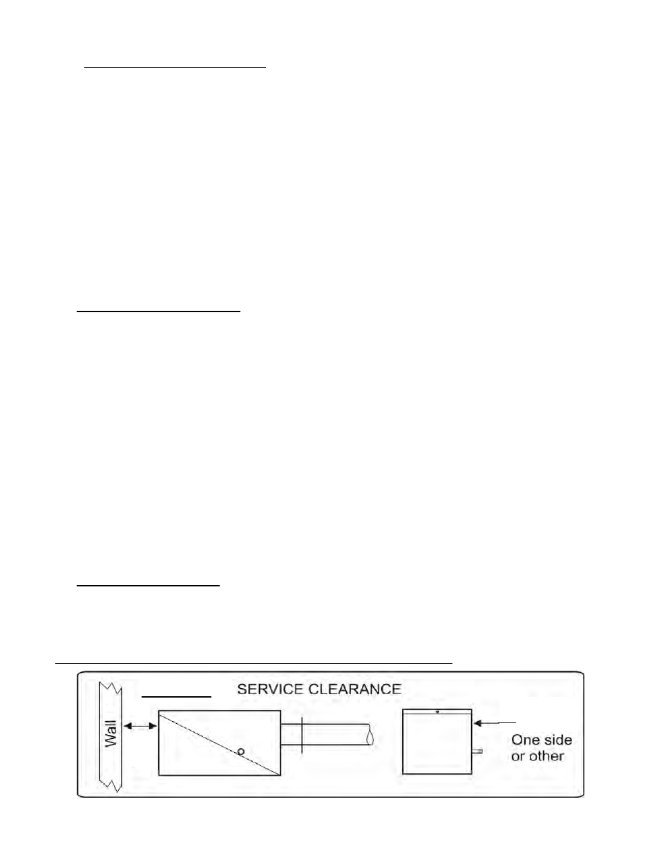
8. SERVICE CLEARANCE: The lower ‘jaw’ of the burner cabinet swings down to provide con-
venient service access to burner components. Provide a minimum clearance from any wall or
obstruction of 6 inches (15 cm) to the access end of the burner housing, and a minimum of 24
inches (61 cm) to any ONE side to allow burner service. (see Figure 2 below)
The minimum clearances to combustibles must always be maintained.