Setting the communications, Communications connections, Com1 rs-232 connection – SATEC RDM172 Quick Start-2 User Manual
Page 11: Pm172 quick start guide, Series pm172 powermeters, Connector 9-pin d-type female
PM172 Quick Start Guide
Series PM172 Powermeters
11
Setting the Communications
You communicate with the meter via a changeable COM1 communication port, or
through a second factory set serial RS-485/RS-422 COM2 port.
Communications Connections
Several communication options are available for the PM172:
• COM1 (check the label on the back of your meter):
RS-232/RS-422/RS-485
56K Dial-up modem
Ethernet 10/100BaseT
Profibus DP
• COM2:
RS-422/RS-485
The RS-232/RS-422/RS-485 port is the standard port for COM1. Other options are
ordered separately. Connections to the Ethernet RJ45 connector and to the
telephone RJ11 connector are made through a cable adaptor provided with your
meter (if ordered).
A full description of the communication protocols is found in the PM172 protocol
guides provided with your meter.
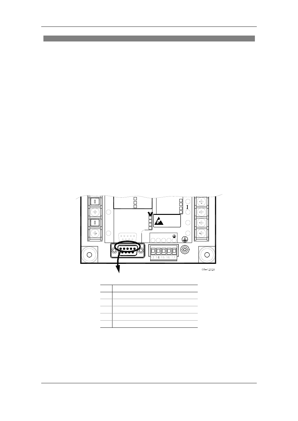
COM1 RS-232 Connection
0-1mA
0-20mA
V
-+1mA
LOW DC
N
(24) 18-36VDC
(48) 36-72VDC
S
2
(12) 10-16VDC
+
7
3
9
6
5
1
-
4-20mA
9
8
COM.1 :
ATTENTION
Devices
Static-Sensitive
Static-Safe
Workstations
Handle Only at
POWER SUPPLY
RS-422/RS-485
16
+RX
COM.2
COM.1
11
V
15
13 14
6
9
N
1
5
-TX
+TX
-RX
V
MODEM
PROFIBUS
ETHERNET
RS-232/422/485 STANDARD
3
17
12
L/+
N/- 10
ANALOG IN/OUT :
Connector 9-pin D-type female:
Pin Signal
1 RS-232
RTS
2 RS-232
RxD
3 RS-232
TxD
4 RS-232
CTS
5
RS-232 Signal ground
To configure the PM172 communication via PAS:
1. Select Configuration from the Tools menu.
2. Under the Communication group of the Instrument Setup tab, select the
type of a connection for your device.
3. Set the device communication address you assigned to the PM172.