Electrical installation, 2 electrical installation, Communications – SATEC AX-8 User Manual
Page 9
6
AN
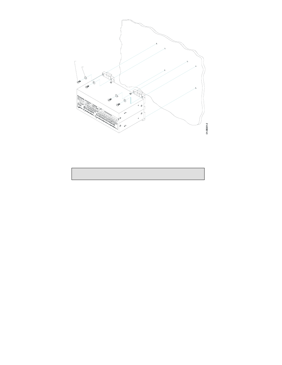
ALO
G E
XPA
NDE
R A
X-8
PA
NEL
LOCK WASHER
SCREW
Figure 3-2 Wall Mounting
3.2 Electrical
Installation
For AX-8 connections to the power supply, communications and analog
outputs, see Figures 3-3 (RS-422 network) or 3-4 (RS-485 network).
IMPORTANT: It is recommended to solder the wire ends
before attaching them to the connectors.
Power Supply
Use a dedicated breaker from a proper power source, from which the unit
can be turned off. All AX-8 analog outputs are provided with an internal
power supply; no external power supply for analog outputs is required.
Communications
The AX-8 is connected on one side to the Powermeter via the RS-422
input, and from the other side, to the multi-drop communication network
via the RS422 or RS-485 output, using the ASCII, Modbus or DNP3.0
protocol.
Communications may be over a distance of up to 1000 meters and at a
baud rate of up to 19,200 bps. A twisted pair cable of 0.33mm
2
/22AWG is
recommended.