S&S Cycle In-Tank Fuel Pump User Manual
Page 3
3
Mounting and Installation Guidelines
1. In new installations, carefully consider the mounting location of the fuel pump and fuel inlet filter. Below are some guidelines for choosing
the best location:
2. The fuel inlet filter should be located in the lowest portion of the tank to ensure sufficient fuel flow as the tank empties. For example, consider
the orientation of the motorcycle when placed on its side-stand. The lowest portion of the tank will usually be on the same side as the side-
stand.
3. As with the inlet filter, the pump itself should be mounted in a low portion of the tank to ensure that it is sufficiently surrounded in fuel as the
tank empties. This is to provide cooling for the pump.
4. The pump outlet should be located so that it and the fuel line will have adequate clearance from hot or moving surfaces and electrical
hardware. The fuel line should clear all rough or sharp engine surfaces to avoid chafing. The line should have at least one bend to allow for
relative motion of the engine with the tank.
5. Occasionally the tank must be raised without complete removal to allow access for service work. Be sure enough slack is used in fuel and
electrical connections to make this possible.
6. Ensure proper venting of the tank. The fuel tank must be properly vented to ensure that air can enter the tank to replace the fuel that exits. If
the unit is installed on an emissions controlled vehicle, be sure that the tank vent is routed according to applicable laws.
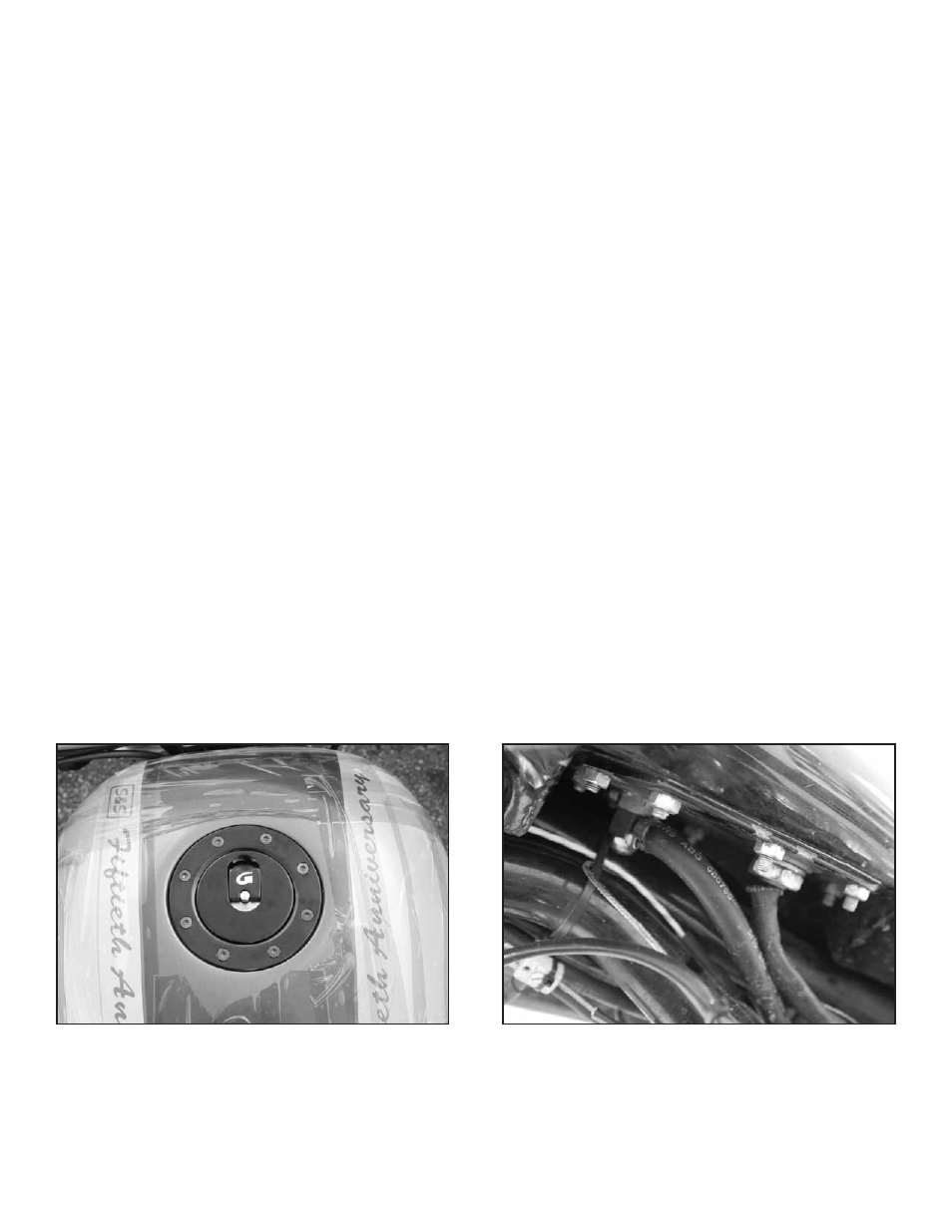
7. The pump should be installed for ease of service. Below are 3 general methods for mounting the fuel pump (See Figures 2 and 3):
a. Through a hole in the top of the tank (minimum 3½" diameter recommended): With this method, only two holes at the bottom of the tank
are required for the fuel outlet and electrical connections (see template at the end of the instruction sheet).
b. With a custom flange or mounting plate attached to the bottom of the tank: Generally, an access hole is cut in the bottom of the tank and
a ring with tapped holes or studs is made and welded in the access hole. If you are using tapped holes, it is recommended that they are
blind to eliminate additional leakage path(s) for the fuel. The pump is then assembled onto an access/mounting plate and the assembly
is fastened to the ring with a gasket/sealant. Before installing, be sure that all gasket surfaces are smooth and even. To prevent leakage,
additional sealant can be applied to the mounting plate fasteners if blind holes were not created on the mounting ring.
c. Through a hole in the side of the tank: As with the “top of the tank” method, only two holes are required at the bottom of the tank for the
fuel outlet and electrical connections. An access hole is cut into the side of the tank (i.e. backbone tunnel) and a ring with studs or tapped
holes is made and welded into the tank’s access hole. A cover plate is then fabricated and fastened to the ring with a gasket/sealant. Before
installing, be sure that all gasket surfaces are smooth and even. Again, sealant should be applied to the fasteners if blind holes were not
incorporated into the ring.
NOTE: There is a template for mounting the fuel pump at the end of this instruction sheet.
Figure 2: Tank with top access hole
Figure 3: Custom mounting plate at bottom of the tank