S&S Cycle Super Stock Ignition System Diagnostic Cable User Manual
Page 3
NOTES:
• Checking the engine rebuild box and writing it to the module will void
your warranty.
• Unchecked RPM break in limit will void your warranty.
• If you wish to check the engine rebuild box, or to disable/able the break
in RPM limit, call the S&S® Tech line for the password. The password is
entered in the options menu.
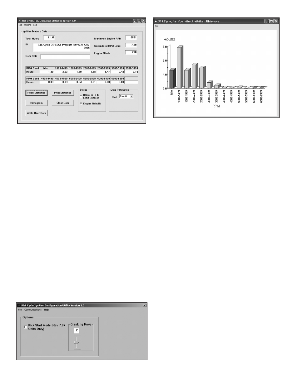
Total hours represents the total time that the engine was running. ID
represents the firmware identification. This field typically includes the
manufacturer, model number, program revision and author’s initials,
and date. Note that the date is not a manufacturing date code, just the
date for the particular firmware release.
Elapsed time is displayed for 13 RPM bands from idle to 6999 RPM.
Note that elapsed time data is rounded off during each engine run, so
the sum of the elapsed time figures may not precisely match the total
hours. The program also displays the maximum engine RPM limit (in
seconds for better resolution) and the number of engine starts.
Clicking on the Clear Data button clears all data displayed on the
screen. Clicking on the Print Statistics button prints a report. When you
click on this button, a small data entry screen pops up and allows you
to add a serial number or comment that will appear on the printout.
You can also use the Print command from the File menu.
A user data field allows you to enter up to 32 alphanumeric characters
in this field. User data is stored in the module EEPROM and can be
used to represent information such as a serial number. User data is
automatically read and displayed whenever you click on Read Statistics.
If no valid user data has previously been written to a module, some
garbage characters may appear in this field. You can enter new data or
edit the existing data. When you click on the Write User Data button,
the data is written to the module.
The elapsed time data in the various RPM bands can be displayed in the
form of a histogram chart (Fig. 4, above) by clicking on the Histogram
button. Color coding of the bars helps to interpret the data. The idle
RPM band is blue, normal operating RPM bands are green and high
RPM bands are yellow and red. The chart is automatically scaled for
best display. You can print the chart along with a complete statistics
report by using the Print Command from the File menu at the top of
the chart window.
FUNCTION OF CONFIGURATION UTILITY
NOTE: The configuration utility allows the user to change to kick start or
electric start modes.
1. Verify that the switch on the harness adapter box is switched to S&S®
Super Stock® Ignition.
2. Connect the black wire with alligator clip to chassis ground and the
Packard Weather Pack connector with brown wire and alligator clip
to the brown tach wire from the Super Stock module.
3. Launch the configuration utility program on your computer by
clicking on the shortcut on your desktop.
4. The main screen appears as shown in the Figure 5.
5. Turn the ignition key and engine run/stop switch to provide power
to the ignition. Do not start the motorcycle.
6. Select the correct com port you have set up on your computer.
7. Select Communications, Port Setup. Choose correct com port you
have set-up on your computer.
8. Select Communications and download from EEPROM.
3
Figure 3
Figure 4
Figure 5