S&S Cycle Ignition System For All 1999–03 Carbureted Harley-Davidson Twin Cam 88 Engines User Manual
Page 6
6
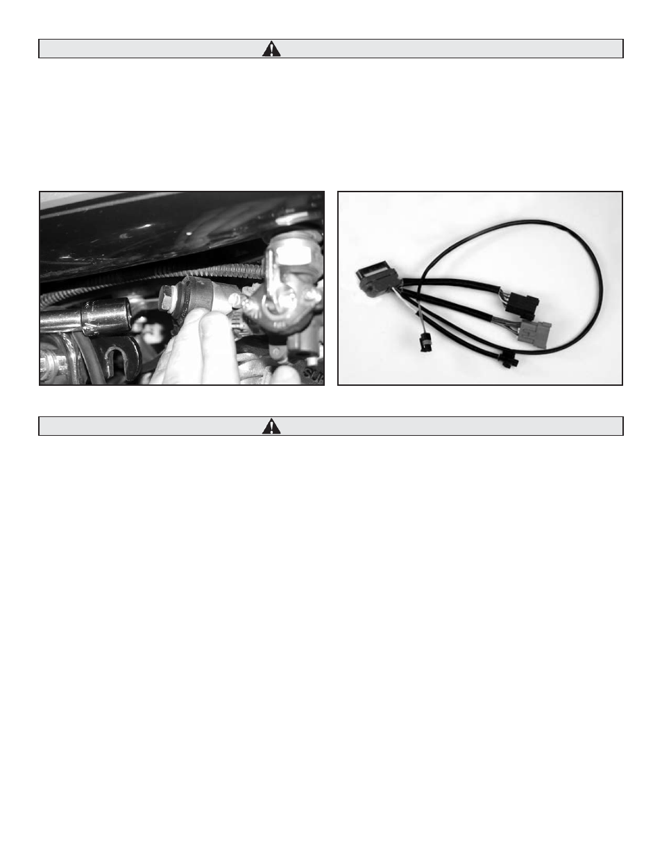
Carefully place fuel tank back into position to check Knock Sensor and mounting block clearance. Position the mounting block so that
the Knock Sensor or mounting block does not contact the fuel petcock or any other part of the motorcycle. If the wiring harness or outer
body of the Knock Sensor (black plastic portion) contacts the engine or any other part of the motorcycle, it could damage the Knock
Sensor, or interfere with its ability to detect knock. See Picture 8, below left. Special care for rubber mounted motors must be given.
View Knock Sensor while motor runs to make sure it has proper clearence.
3. After determining final position for Knock Sensor, remove mounting bolts and lockwashers, then re-install them on mounting block
bolt (k), torque to 33 ft-lbs., and Loctite® 243 on knock sensor bolt (j), torque to 11 ft-lbs.
Hold knock sensor in position by hand only while torquing. Do NOT use pliers. Damage to knock sensor will occur.
3. Installation of the IST Ignition Module and Wiring Harness Adapter:
The Wiring Harness Adapter for Harley-Davidson® Twin Cam 88® (See Picture 9, above right) is a one-piece assembly consisting of the
following connectors:
• (a) IST Ignition Module Connector: 32-Socket, Gray (Delphi®/Packard® #12129025) - Connects to the S&S® Intelligent Spark Technology
Ignition Module.
• (b & c) Motorcycle Main Harness Connectors: (1) 12-Pin, Gray (Deutsch #DT04-12PA) & (1) 12-Pin Black (Deutsch #DT04-12PB) – Connects to
the stock Harley-Davidson® wiring harness in place of the stock module.
• (d) Knock Sensor Connector: 2-Socket (Bosch #1928403192)
• (e) Head Temperature Sensor Connector: 2-Socket (Delphi®/Packard® #12162193)
NOTE: Locking tabs on each connector listed should produce a light clicking sound when properly assembled. S&S recommends checking each connection
by lightly pulling on each half of the connector to insure that the locking tabs have properly seated.
The IST ignition module includes a hardware packet. The hardware is intended for spacing the module and the connector off of the
mounting back plate. Washers are also included for the mounting screws. This hardware is only necessary on some models. The hardware
packet includes the following spacers and washers:
• .200" spacers (4)
• .060" spacers (4)
• .475" OD washers (2)
• .250 ID lockwashers (2)
b
c
d
e
a
Picture 9
Picture 8
CAUTION
CAUTION