S&S Cycle Standard and Easy Start Chain Drive Camshafts for 2006 Harley-Davidson Dyna models and all 2007-up Big Twins User Manual
Page 4
4
1. Remove pushrods.
a. Remove pushrod cover clips with a small screwdriver and
compress pushrod covers to expose pushrods. Lift rear tire of
motorcycle with a suitable jack. Rotate the engine until one
of the cylinders is on “top dead center compression stroke”
(TDCC). TDCC can be found by rolling the rear tire forward
while watching or feeling the pushrods move through their
travel. When BOTH pushrods are at the lowest point of their
travel and the piston for that cylinder is at TDC, the engine is
at TDCC. Rotate the pushrods to ensure there is no load on
them. If the pushrods will not rotate freely by hand, either
the engine is not on TDCC, or the lifters need to bleed down.
It may be necessary to let the lifters bleed down for a few
minutes before the pushrods will rotate freely.
b. If stock non-adjustable pushrods will not be re-used, they
may be removed by cutting them. When cutting pushrods,
S&S recommends a bolt cutter be used as it is the cleanest
method. Be sure to only cut the pushrods that are not loaded
and rotate freely by hand.
c. If stock one piece pushrods are to be re-used, they must be
removed using the factory procedure. Remove the gas tank
and rocker box covers. Remove the rocker arm support by
first removing the two smaller bolts which hold the breather
cover in place. Next break loose the four bolts holding the
rocker arm support plate in place with an alternating pattern.
Remove the four rocker arm support plate bolts, and then
the rocker arm support assembly. The pushrods may now
be removed by sliding them up into the head slightly and
then pulling the bottom of the pushrod towards you. Mark
the original pushrod location as it is removed to ensure it is
replaced in its original position. The intake pushrod is shorter
than the exhaust pushrod. Interchanging the intake and
exhaust pushrods upon reassembly, will cause the intake
valve to stay open on the compression stroke and the engine
will not run.
d. Rotate the engine so the other cylinder is on TDC
compression and repeat the above procedure.
2. Remove cam cover and gasket. Secure lifters with a magnetic
tappet tool or a tool made from a large binder clip spring. See
Picture 2, below.
3. Rotate rear wheel to align timing marks on the primary cam
chain.
4. Remove the primary chain tensioner by removing the two
retaining bolts and install sprocket locking tool.
5. Remove the crank sprocket bolt and flat washer.
6. Remove rear cam sprocket bolt and flat washer.
7. Remove sprocket locking tool.
8. Gently pry off crank sprocket and rear cam sprocket.
Cam Support Plate and Cam Removal
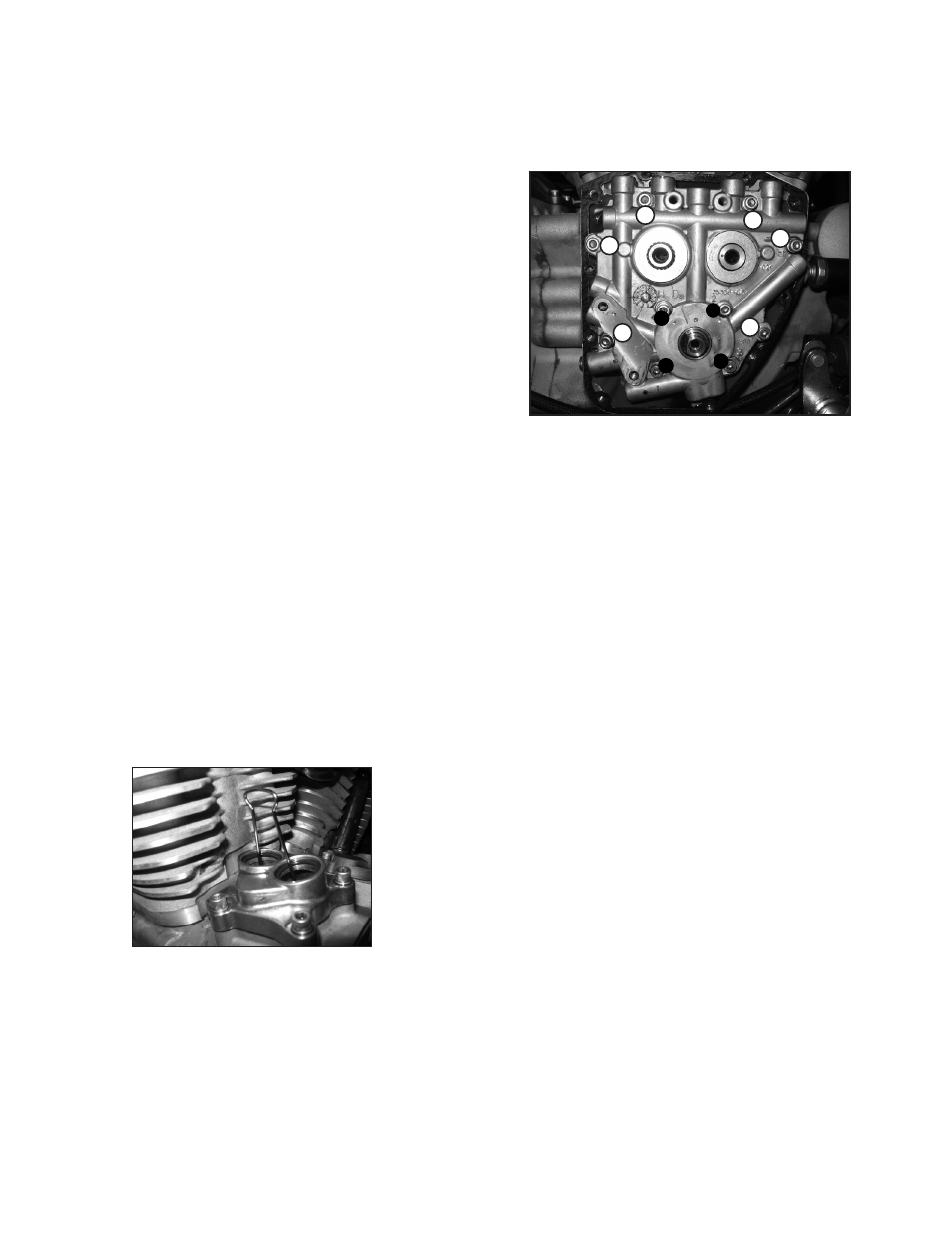
1. Gradually loosen and remove the four oil pump bolts/washers
according to the sequence shown in Picture 3, below.
2. Gradually loosen and remove the six support plate bolts/
washers according to the sequence shown below.
3. Remove spacer from rear cam, this spacer is thicker than the
front spacer.
4. Remove cam plate and cams from engine.
5. Remove retaining ring and spacer from front cam. This spacer is
0.100" thick.
6. Remove the secondary cam chain tensioner.
7. Remove the cams and cam chain. Mark the direction of the cam
chain so that it is installed in the original direction of rotation
with the new cams.
Reassembly
Crankcase Preparation
1. When using 551G, 570G, 583G, 585G, 625G, or 640G camshafts
clearance between the pinion bearing boss and the rear cam
lobe must be checked. See Pictures 4 & 5, top of next page.
Remove just enough material to provide .030" of clearance
between the top of the cam lobe and the pinion bearing boss
when the camshafts are rotated in the inner needle bearing.
Also check clearances between the cam lobe and the tappet
guide bosses. To avoid contamination of the engine with chips,
we recommend that all holes in the gear case be taped off with
duct tape and that the gear case be thoroughly cleaned with
parts cleaner or solvent after clearancing is performed.
2. Replace inner cam needle bearings. Be sure to use a full
complement needle bearing such as those supplied with the
chain drive installation kit. These bearings offer a higher load
carrying capacity associated with high lift camshafts. Refer to
the H-D® service manual for proper installation procedure.
NOTE: Before reinstalling cam support plate, replace oil pump scavenge
o-ring (supplied in kit) even if the original appears to be in good condition.
The stock o-ring can become brittle and provide a poor seal if reused. This
can cause poor oil scavenging, oil carry-over and loss of power.
Picture 3
1
4
2
6
3
5
1
2
3
4
Picture 2