RKI Instruments GD-K71D User Manual
Page 12
PT2E-1052
11
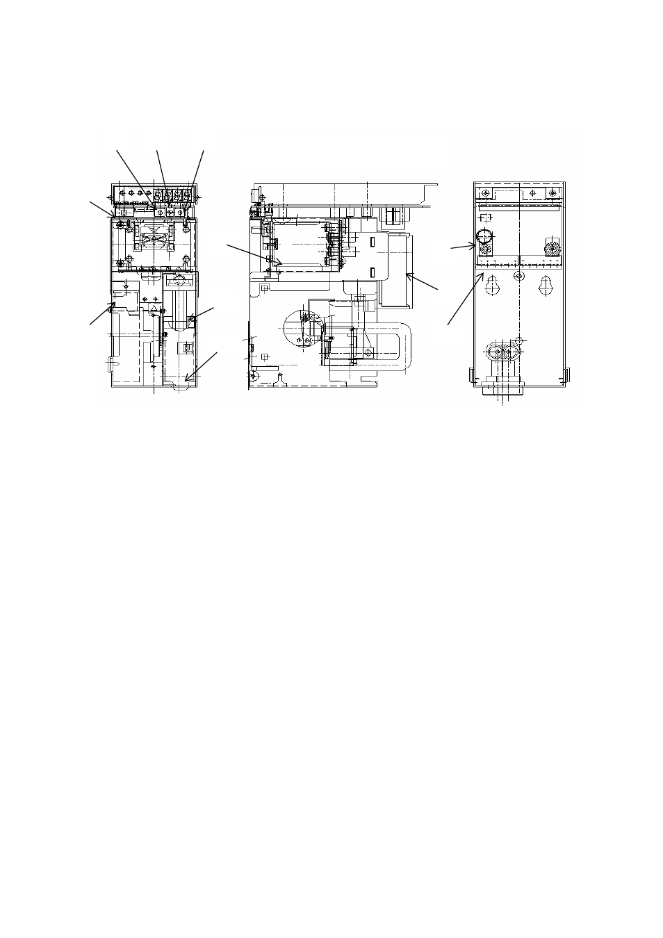
3−4−2.Inside view
【Front view of detector unit】 【Front view of wall mounting unit】
⑩Power switch (POWER)
…… ON/OFF switch for power supply(24VDC).
⑪Fuse
……………………….. Fuse for power
⑫MODE switch (Grey)
…………. Switch that changes from detection mode to maintenance
mode and changes the mode back to the detection mode.
⑬TEST/SET switch(Red)
……… Switch that turns the mode into the alarm testing mode, and
sets the further mode during the maintenance mode.
⑭FLOW ADJ./▲▼switch
…….. Switches that adjust the flow rate, looking at the flow
monitor. Or, these are used to choose the items at the
maintenance mode, to adjust the zero point, span point and
to increase the indication at alarm testing.
⑮Pump
………………………... To sample the detection gas.
⑯Lithium battery
……………… For back-up of the sensor.
⑰Sensor
………………………... To detect the sampled gas
⑱Detector unit removing lever
… Bring down this lever to remove the detector unit.
⑲Terminal plate
………………... To connect external cables
⑳Flowmonitor
…………………. To confirm sample flow rate.
⑩
⑫
⑪
⑭
⑬
⑮
⑯
⑰
⑱
⑲
⑳
【Side view of detector unit】