Description, Oxygen detector, Amplifier – RKI Instruments 65-2513RK User Manual
Page 6
2 • 65-2513RK Oxygen Transmitter
Description
This section describes the components of the oxygen transmitter. The transmitter consists
of the oxygen detector, amplifier, and junction box.
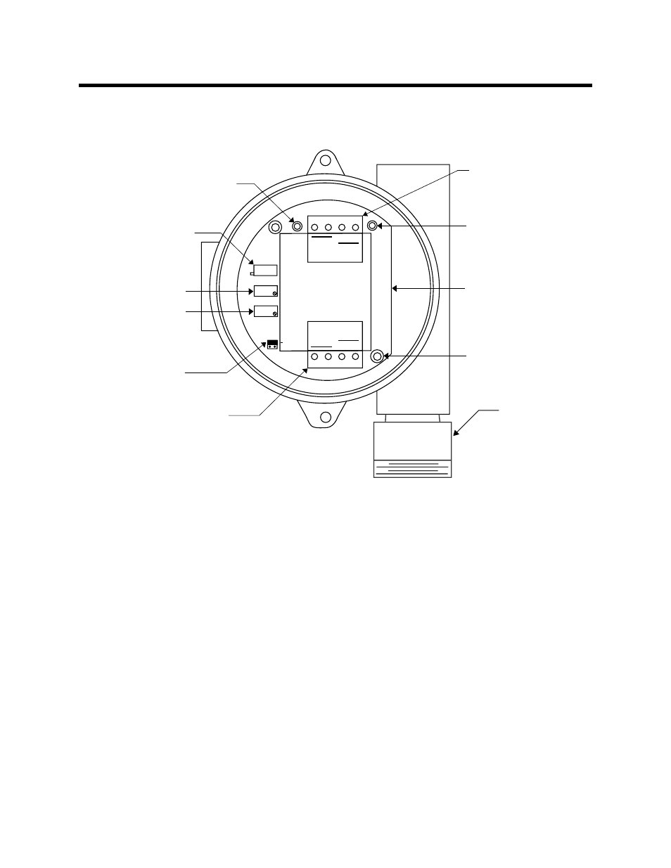
Figure 1: Oxygen Transmitter Component Location
Oxygen Detector
The detector’s sensing element along with signal conditioning components are
encapsulated within a conduit mounting black anodized aluminum housing. The sensing
element used is a capillary type that is not susceptible to output changes with changes in
atmospheric pressure. Through a series of chemical and electronic reactions, the detector
produces a millivolt output that is proportional to the detection range. 3/4” NPT
mounting threads at the top of the detector allow you to mount the detector to the
junction box or a 3/4” NPT conduit fitting. Two color-coded leads extend from the top of
the detector. The leads allow you to connect the detector to the amplifier.
Amplifier
The amplifier converts the millivolt output from the oxygen detector to a 4 - 20 mA signal
that is proportional to the detection range and transmits the signal to the controller via 2
wires. The amplifier includes the amplifier type selector, detector terminal strip,
interconnect terminal strip, span pot, zero pot, and test points (see Figure 1).
Amplifier Type Selector
The amplifier type selector is near the bottom left corner of the amplifier. It is below the
span pot and to the left of the detector terminal strip.
Oxygen detector
Test point (+)
Test point (-)
Zero potentiometer
Span potentiometer
Securing screw (2)
Oxygen amplifier
Amplifier type
selector
OXYGEN
ZERO
SPAN
Potentiometer
(factory-set)
Interconnect
terminal strip
4/20
FB
+
24V
POWER/SIG
Detector
terminal strip
Not
Used
OXY
W
G
SENSOR
TP
-
TP
+
Not
Used