Description, Co detector – RKI Instruments 65-2435RK User Manual
Page 5
65-2435RK CO Transmitter • 5
Description
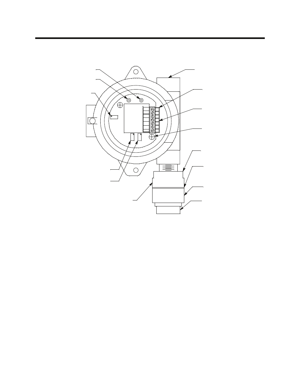
This section describes the components of the CO transmitter. The transmitter consists of the CO
detector, amplifier, and junction box.
Figure 1: CO Transmitter Component Location
CO Detector
The CO detector includes the detector housing and sensor.
Detector Housing
The detector housing protects the sensing components within the housing. Use the mounting
threads at the top of the housing to screw the CO detector into the bottom conduit hub of the
junction box. Use the removable cap near the bottom of the housing to access the sensor for
maintenance or replacement. The cap protects the sensor from damage and includes a flame
arrestor which contains any sparks which may occur within the detector housing. Two cap gaskets
seal the interface between the housing and cap.
Two wires extend from the top of the detector housing. Use these wires to connect the CO detector
to the amplifier. The housing includes a four-socket pattern. This socket pattern accepts the sensor’s
four pins to secure the sensor within the detector housing. A pre-amplifier, located between the
sockets and two interconnect wires, conditions the sensor’s signal before the signal reaches the
amplifier.
Sensor
The sensor is secured within the sensor housing by the four pins. Through a series of chemical and
electrical reactions, the sensor produces an electrical output that is proportional to the detector
range of the transmitter.
Null
Potentiometer
Cap Gasket (x2)
Detector Housing Cap
Securing Screw (2)
Carbon Monoxide
Amplifier
Carbon Monoxide Detector
Flame Arrestor
Terminal Strip
Test Point (-)
Test Point (+)
3/4" Conduit Hub
Detector Housing
Span Potentiometer
Zero Potentiometer
F B
2 4V
T P+
N UL L
SPAN
R ED
PW
R
T P
Z ER O
SE
N
S
O
R
4 -2 0 mA T ra n sm itte r
5 7 -12 5 2R K
B LK
G RN
B RN
W H T