RKI Instruments 65-2435RK User Manual
Page 15
65-2435RK CO Transmitter • 15
9. Reconnect the wiring from the controller to the interconnect terminal strip as shown in Table 2
and Figure 3, Wiring the CO Transmitter to a Controller.
10. Reconnect the detector leads to the detector terminal strip as shown in Table 3 and Figure 3,
Wiring the CO Transmitter to a Controller.
11. Reinstall the junction box cover.
12. Turn on or plug in incoming power at the power source end.
13. Turn on the controller.
CAUTION: Allow the sensor to warm up for 5 minutes before you continue with the next step.
14. Calibrate the CO transmitter as described in the Calibration section of this manual.
Replacing the CO Detector
NOTE: In most cases, it is only necessary to replace the CO sensor.
1. Turn off the controller.
2. Turn off or unplug incoming power at the power source end.
3. Remove the junction box cover.
4. Disconnect the detector leads from the detector terminal strip. Note the position of the color-
coded leads as you remove them.
5. Unscrew the detector from the junction box.
6. Guide the detector leads of the replacement detector through the bottom conduit hub of the
junction box, then screw the mounting threads of the detector into the conduit hub.
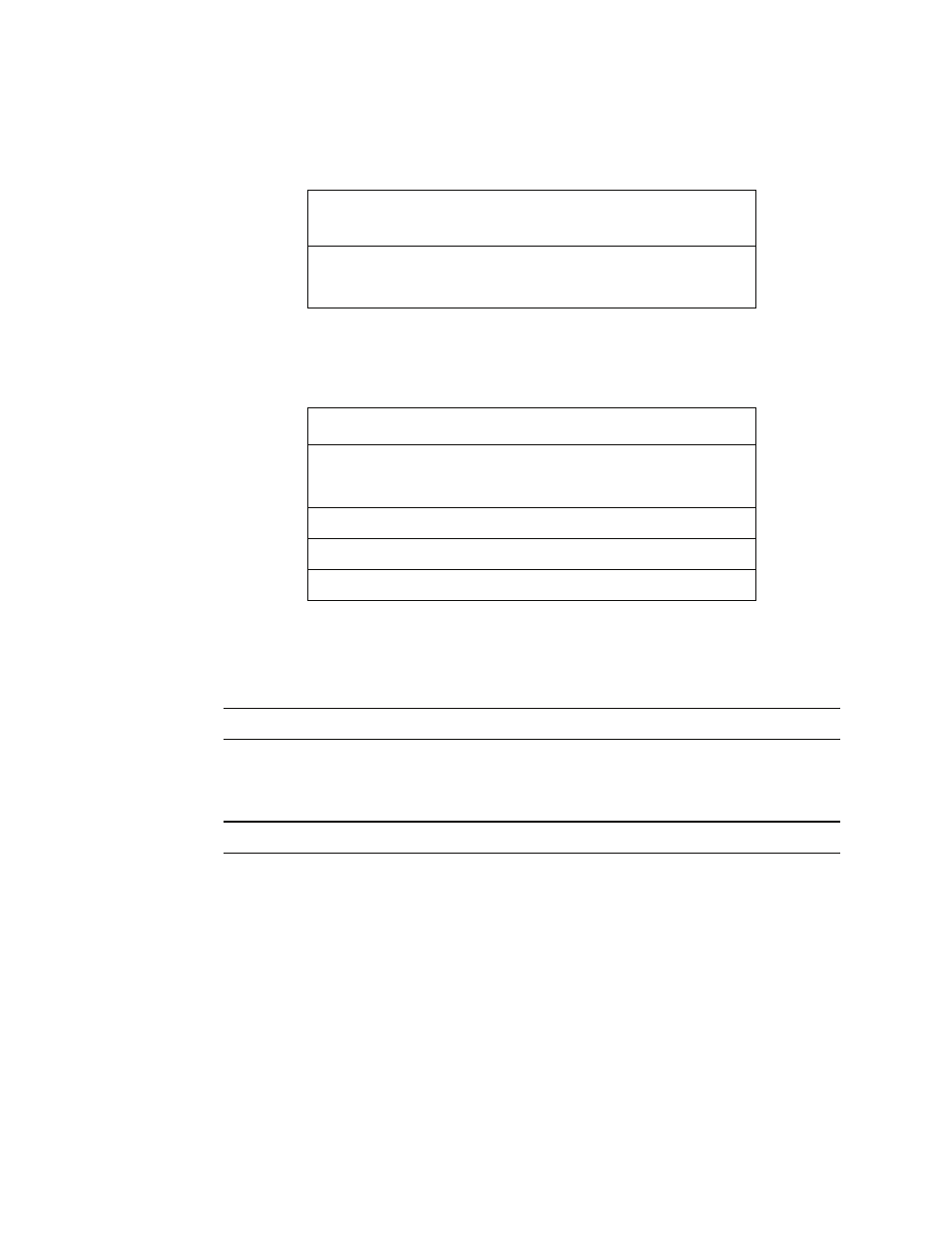
Table 2: Reconnecting the CO Amplifier to a Controller
Amplifier Terminal Strip
Controller Transmitter
Terminal Strip (typical)
FB
4 -20 (FB)
24V
+ V (19 - 30 VDC)
Table 3: Reconnecting the CO Detector to the Amplifier
CO Detector Lead
Amplifier Terminal Strip
Black
BLK
Green
GRN
Brown
BRN
White
WHT
Red
RED