Description, Combustible gas detector – RKI Instruments 65-2400RK User Manual
Page 6
2 • 65-2400RK Combustible Gas Transmitter
Description
This section describes the components of the combustible gas transmitter. The transmitter
is a 4 - 20 mA type detector head. It consists of the combustible gas detector, amplifier, and
junction box.
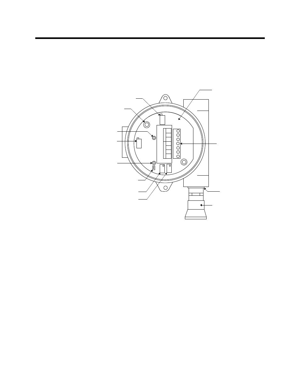
Figure 1: Combustible Gas Transmitter Component Location
Combustible Gas Detector
The combustible gas detector includes the sensing elements, flame arrestor, detector
housing, and detector leads.
Sensing Elements
Two sensing elements are protected within the detector assembly. Through a series of
thermal and electronic reactions, these elements produce an electrical output that is
proportional to the detection range of the transmitter.
Flame Arrestor
The porous flame arrestor allows the target gas to diffuse into the detector assembly and
contact the sensing elements. The flame arrestor also contains sparks within the detector.
GND
24V
4-20
RED
WHT
GRN
BLK
SENSOR
POWER/SIG
TP+
TP-
Combustible gas
amplifier
Interconnect
terminal strip
Test point (-)
Securing screw (2)
Test point (+)
Reducer
(3/4 in. x 1/2 in.)
Combustible gas
detector
Zero potentiometer
Span potentiometer
Potentiometer
(
factory set)
Potentiometer
(factory set)
Jumper pins
(factory use only)