Calibration frequency – RKI Instruments 65-2400RK User Manual
Page 17
65-2400RK Combustible Gas Transmitter • 13
8.
Place the new amplifier in the same position as the amplifier you removed in the
previous step.
9.
Use the two screws you removed in step 5 to secure the amplifier to the junction box.
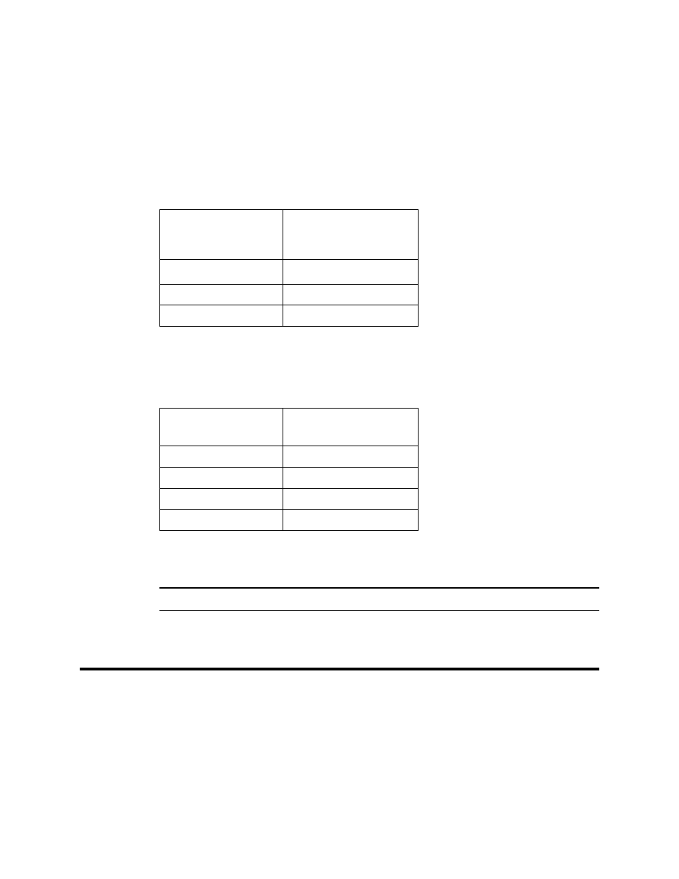
10. Reconnect the wiring that connects the controller to the combustible gas transmitter at
the amplifier’s interconnect terminal strip as shown in Table 4 below and Figure 3 on
page 7 of this manual.
11. Reconnect the detector leads to the amplifier’s interconnect terminal strip as shown in
Table 5 below and Figure 3 on page 7 of this manual.
12. Turn on power to the controller.
13. Turn on the controller and place it into normal operation.
CAUTION:
Allow the detector to warm up for 5 minutes before you continue with the next step.
14. Calibrate the combustible gas transmitter as described in “Calibration” on page 14 of
this manual.
Calibration Frequency
Although there is no particular calibration frequency that is correct for all applications, a
calibration frequency of every 3 to 6 months is adequate for most combustible gas
transmitter applications. Unless experience in a particular application dictates otherwise,
RKI Instruments, Inc. recommends a calibration frequency of every 3 months.
If an application is not very demanding, for example detection in a clean, temperature
controlled environment where combustible gas is not normally present and calibration
Table 4:
Reconnecting the Combustible Gas Amplifier
to the Controller
Amplifier Interconnect
Terminal Strip
Controller
Transmitter Terminal
Strip (typical)
GND
- (DC -)
4-20
4 - 20 mA (FB or S)
24V
+ 24V
Table 5:
Reconnecting the Combustible Gas
Detector to the Amplifier
Detector Lead
Amplifier Interconnect
Terminal Strip
Red
RED
White
WHT
Green
GRN
Black
BLK