RKI Instruments 65-2400RK User Manual
Page 16
12 • 65-2400RK Combustible Gas Transmitter
Replacing Components of the Combustible Gas Transmitter
This section includes procedures to replace the combustible gas detector and amplifier.
Replacing the Combustible Gas Detector
1.
Turn off power to the controller.
2.
Place the controller’s power switch in the OFF position.
3.
Remove the junction box cover.
4.
Disconnect the detector leads from the interconnect terminal strip. Note the position
of the color-coded leads as you remove them.
5.
Unscrew the detector from the junction box.
6.
Guide the detector leads of the replacement detector through the bottom conduit hub
of the junction box, then screw the mounting threads of the detector into the conduit
hub.
7.
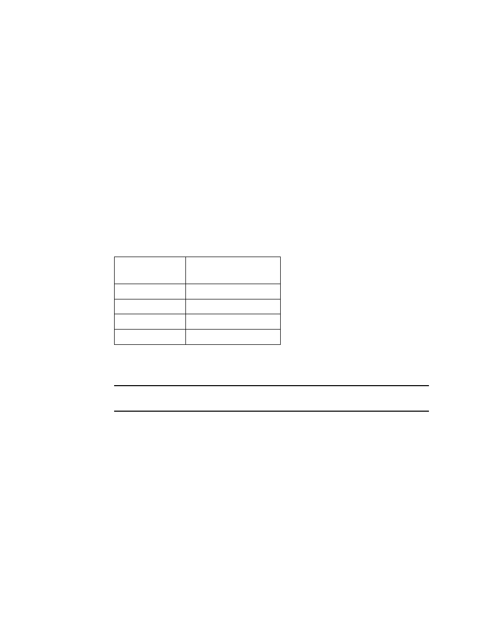
Connect the detector leads to the interconnect terminal strip as shown in Table 3
below and Figure 3 on page 7 of this manual.
8.
Turn on power to the controller.
9.
Place the controller’s power switch in the ON position.
CAUTION:
Allow the replacement detector to warm up for 5 minutes before you continue with
the next step.
10. Calibrate the replacement detector as described in “Calibration” on page 14 of this
manual.
Replacing the Amplifier
1.
Turn off power to the controller
2.
Place the controller’s power switch in the OFF position.
3.
Remove the junction box cover.
4.
Disconnect the detector leads from the interconnect terminal strip.
5.
Disconnect the wiring that connects the combustible gas transmitter to the controller
from the amplifier’s interconnect terminal strip.
6.
Unscrew and remove the two screws that secure the amplifier to the junction box.
The screws are at the top left and bottom right of the amplifier.
7.
Remove the amplifier.
Table 3:
Reconnecting the Combustible Gas
Detector to the Amplifier
Detector Lead
Amplifier Interconnect
Terminal Strip
Red
RED
White
WHT
Green
GRN
Black
BLK