RKI Instruments 65-2330RK User Manual
Page 7
65-2330RK H
2
S Transmitter • 3
H
2
S Detector
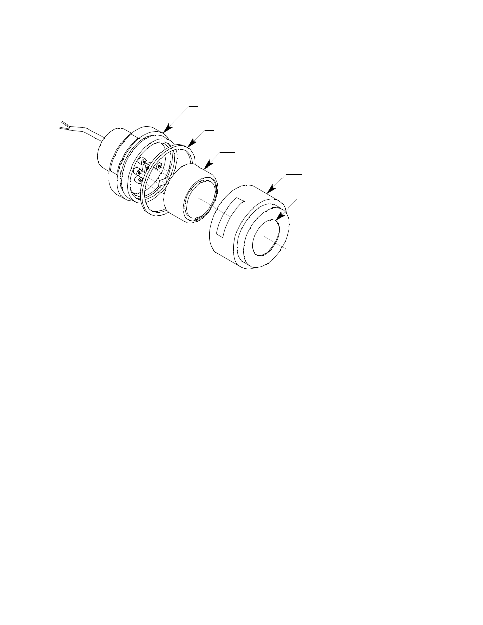
The H
2
S detector consists of the detector housing body, detector housing cap, cap gasket,
and the plug-in sensor.
Figure 2: H
2
S Detector Component Location
Detector Housing Body
The detector housing body protects the electronic components within the housing. Use the
mounting threads at the top of the housing to screw the H
2
S detector into the 3/4” NPT
hub on the bottom of the junction box. Two wires extend from the top of the detector
housing body. Use these wires to connect the H
2
S detector to the amplifier. One of the
wires is red and one of the wires is black.
The housing includes a four-socket pattern. This socket pattern accepts the sensor’s four
pins to secure the sensor within the detector housing. A pre-amplifier, located between the
sockets and two interconnect wires, conditions the sensor’s signal before the signal
reaches the controller.
Housing Cap & Cap Gasket
The housing cap screws onto the detector housing. It retains the plug-in sensor and
protects it from damage. A foam gasket inside the housing cap seals against the face of the
sensor when the cap is screwed onto the housing body. A hydrophobic membrane on the
outside of the cap face keeps water and particulates away from the sensor face behind the
cap. Unscrew the detector cap to access the plug-in sensor for maintenance or
replacement. A cap gasket seals the interface between the housing and cap.
Plug-In H
2
S Sensor
The sensor is secured within the detector assembly by the housing cap. Through a series
of chemical and electrical reactions, the sensor produces an electrical output that
corresponds to the detection range of the transmitter.
Detector Housing Cap
Hydrophobic Membrane
Plug-In H2S Sensor
Detector Housing Body
Cap Gasket