Detection system, Sensor the infrared ch – RKI Instruments 35-3010RKA-07 User Manual
Page 9
35-3010RKA-07 Sample-Draw Detector • 5
Flow Blocks
Both flow blocks are located in the lower right corner of the sample-draw detector. The
oxygen and H
2
S sensors are installed in the larger flow block. The smaller flow block
houses the IR CH
4
sensor. The flow blocks route the sampled air to each sensor.
EXHAUST Fitting
The EXHAUST fitting on the bottom of the housing allows the gas sample to exit the
sample-draw detector. The EXHAUST fitting accepts 1/4 in. rigid tubing. See
“Installation” on page 9 to connect tubing to the EXHAUST fitting.
Detection System
The detection system consists of the gas sensors, LEL and oxygen transmitters, preamp
circuit board, and the main circuit board.
IR CH
4
Sensor
The infrared CH
4
sensor is installed in the smaller flow block in the lower right corner. A
small circuit board with a cable mates to it and retains it in the block. The cable is wired to
the main PCB.
Oxygen Sensor
The oxygen sensor is installed in the lower right of the larger flow block. It consists of a
cylindrical body which houses the detection elements and a cable which terminates in a
round 7-pin male connector. The sensor connector mates to a 7-position socket that is
wired to the main PCB.
Carbon Monoxide Sensor
The CO sensor position in the flow block is occupied by a plastic dummy plug in the
35-3010RKA-07.
Hydrogen Sulfide Gas Sensor
The hydrogen sulfide gas sensor is installed in the upper right side of the flow block. It
has 4 pins which mate with sockets in the preamp circuit board.
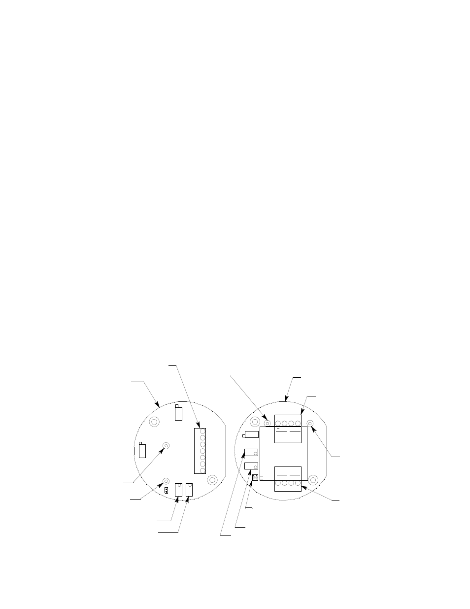
Figure 3: LEL & Oxygen Transmitters
BATT
24 V
Test Point TP-
Sensor Terminal
Strip
Oxygen
Transmitter
FB
+
+
TOXIC
OXY
G
Transmitter Type Selector,
Set To OXY
Interconnect
Terminal Strip
Span Pot
Zero Pot
TP
+
TP
-
4/2 0
TOXIC
Test Point TP+
RD
B K
W
OXY
SPAN
LEL Transmitter
Interconnect
Terminal Strip
Test Point TP-
Span Pot
Zero Pot
ZERO
Test Point TP+