RKI Instruments 35-3010RKA-07 User Manual
Page 11
35-3010RKA-07 Sample-Draw Detector • 7
signal. Since the CO sensor is replaced with a dummy plug in the 35-3010RKA-07 the CO
sensor signal cable carries no signal in this version of the 35-3010RK.
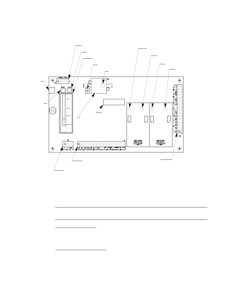
Main Circuit Board
Figure 4: Main Circuit Board
The main circuit board includes the interconnect terminal strip, sensor/transmitter
terminal strip, amp 1 circuit, amp 2 circuit, pump terminal strip, relay, and reset switch
(see Figure 4).
NOTE:
The flowmeter and status lights are mounted to the main circuit board but are
considered part of the flow system.
Interconnect Terminal Strip
The interconnect terminal strip is the sixteen-point terminal strip near the bottom edge of
the main circuit board. Use the interconnect terminal strip to connect the sample-draw
detector to power and an external device.
Sensor/Transmitter Terminal Strip
The sensor/transmitter terminal strip is the sixteen-point terminal strip near the right
edge of the circuit board. Use the transmitter terminal strip to connect sensors or
transmitters to the main circuit board.
Test Point CAL + 2
Amp 1
(CO)
Zero
Span
Zero
Fail LED
Sensor/Transmitter
Terminal Strip
Pressure Switch
Reset
Switch
Pilot LED
Amp 2
(H2S)
Span
Test Point CAL + 1
Test Point CAL - 2
Test Point CAL - 1
AC Terminal
Strip Not Used
Interconnect Terminal
Strip
Low Flow Adjust
Flow Adjust Pot
Flowmeter
Pump Terminal Stip
Relay