Parts list – RKI Instruments 35-3010RK-06-02 User Manual
Page 26
22 • 35-3010RK-06-02 Sample-Draw Detector
3.
Follow the directions in the controller’s operator’s manual for setting the zero reading
for the oxygen channel.
4.
When the instructions call for applying gas to the detector, connect the sample tubing
from the regulator to the inlet line at or near the INLET fitting.
5.
Allow the gas to flow for one minute.
6.
Set the zero reading according to the controller operator’s manual.
7.
Disconnect the sample tubing from the inlet line.
8.
Unscrew the regulator from the 3-gas calibration cylinder.
9.
For convenience, leave the regulator attached to the sample tubing.
Returning to Normal Operation
1.
Reconnect the incoming sample line.
2.
Wait 1 to 2 minutes to allow the calibration gas to be drawn out and the reading to
stabilize.
3.
Close the housing door.
4.
Store the components of the calibration kit in a safe and convenient place.
Parts List
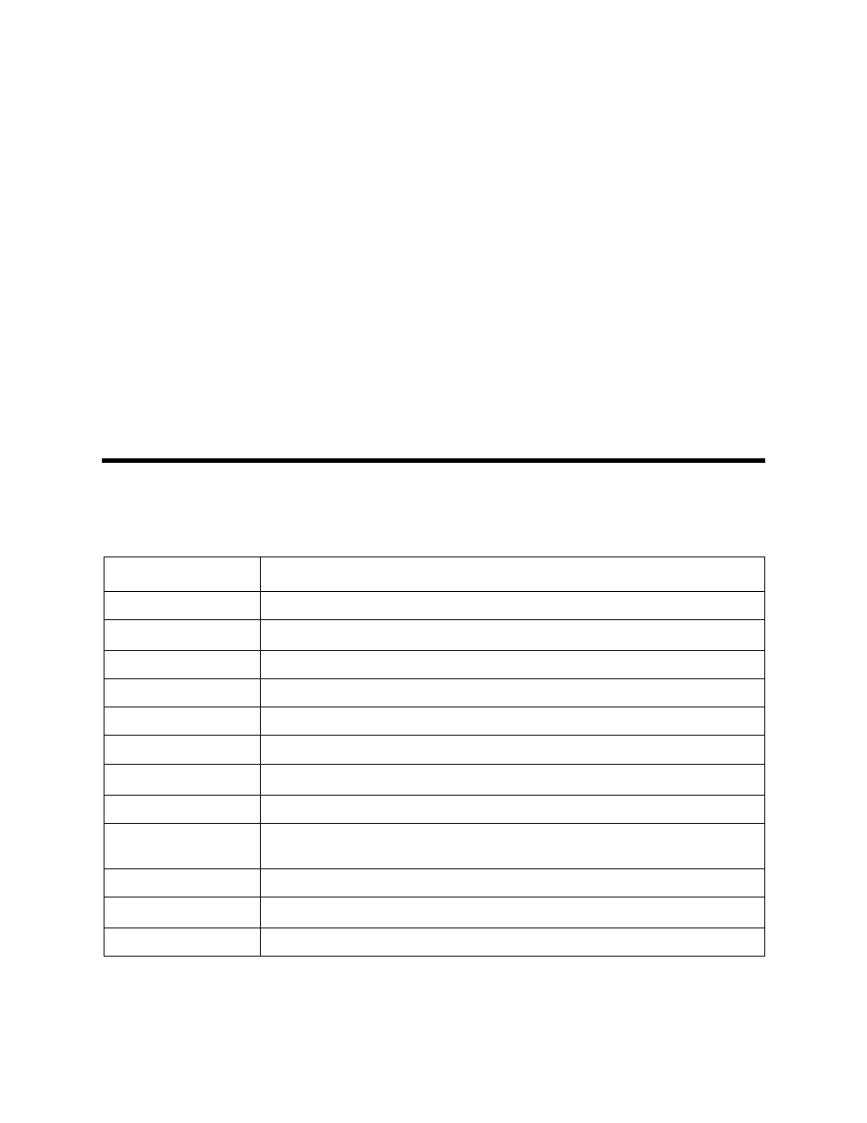
Table 2 lists replacement parts and accessories for the sample-draw gas detector.
Table 2: Parts List
Part Number
Description
06-1248RK-03
Sample tubing, 3/16 x 5/16, 3 ft. length for calibration kit
07-0034RK
Sealing gasket, for CO and H
2
S flow block cavities
30-0610RK
Pump
33-0171RK
Hydrophobic filter (AcroPak)
33-6095RK
Charcoal filter, CF-188
65-0601RK
Oxygen sensor
81-0070RK-01
Calibration cylinder, 2,000 ppm CO
2
in nitrogen, 34 liter
81-0076RK-01
Zero air calibration cylinder (34 liter)
81-0090RK-01
3-gas calibration cylinder, 50% LEL methane/12% oxygen/50 ppm CO, 34
liter
81-1055RK
Regulator, demand flow, for 17 and 34 liter steel cylinders
81-5316RK01DLV
Calibration kit with 3-gas mix and 2,000 ppm CO
2
in nitrogen
ES-1531-CO
CO sensor