Parts list – RKI Instruments 35-3001A-05-02 User Manual
Page 24
20 • 35-3001A-05-02 Carbon Dioxide Sample-Draw Detector
6.
Disconnect the sample tubing from the inlet line.
7.
Unscrew the regulator from the carbon dioxide calibration cylinder.
Returning to Normal Operation
1.
Wait approximately one minute to allow the carbon dioxide reading to stabilize.
2.
Remove the voltmeter leads from the amplifier test points.
3.
Close the housing door.
4.
Follow the instructions in the controller’s operator’s manual to exit the calibration mode.
5.
Store the components of the calibration kit in a safe and convenient place.
Parts List
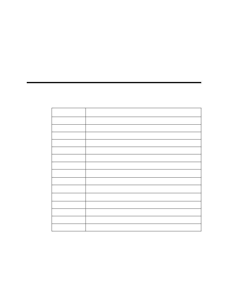
Table 2 lists replacement parts and accessories for the carbon dioxide sample-draw detector.
Table 4: Parts List
Part Number
Description
06-1248RK
Sample tubing, 3/16 in. x 5/16 in., specify length
06-1248RK-03
Sample tubing, 3/16 in. x 5/16 in., 3 feet (for calibration kit)
07-0110RK
Gasket for IR flow block
30-1016RK
Pump
33-0165RK
Hydrophobic filter
33-0167RK
Particle filter
57-1053RK-10
Amplifier
61-5040RK-02
IR CO
2
sensor, 0 - 5,000 ppm
71-0340
Operator’s Manual, 35-3001A-05-02 Sample-Draw Detector
81-0070RK-01
Steel calibration cylinder, 2000 ppm CO
2
, 34-liter
81-0070RK-03
Steel calibration cylinder, 2000 ppm CO
2
, 103-liter
81-0078RK-01
Steel calibration cylinder, 100% nitrogen, 34-liter
81-0078RK-03
Steel calibration cylinder, 100% nitrogen, 103-liter
81-1054RK
Regulator, demand flow, for 58- and 103-liter cylinders
81-1055RK
Regulator, demand flow, for 17- and 34-liter steel cylinders