Not used on t his v ersion, Green black red w hite, 24 vdc controll er or recording dev ice – RKI Instruments 35-3001A-05-02 User Manual
Page 15: 4/20 s ignal - (dc g round) ir c o2 sensor pcb, Ir c o2 sensor
35-3001A-05-02 Carbon Dioxide Sample-Draw Detector • 11
8.
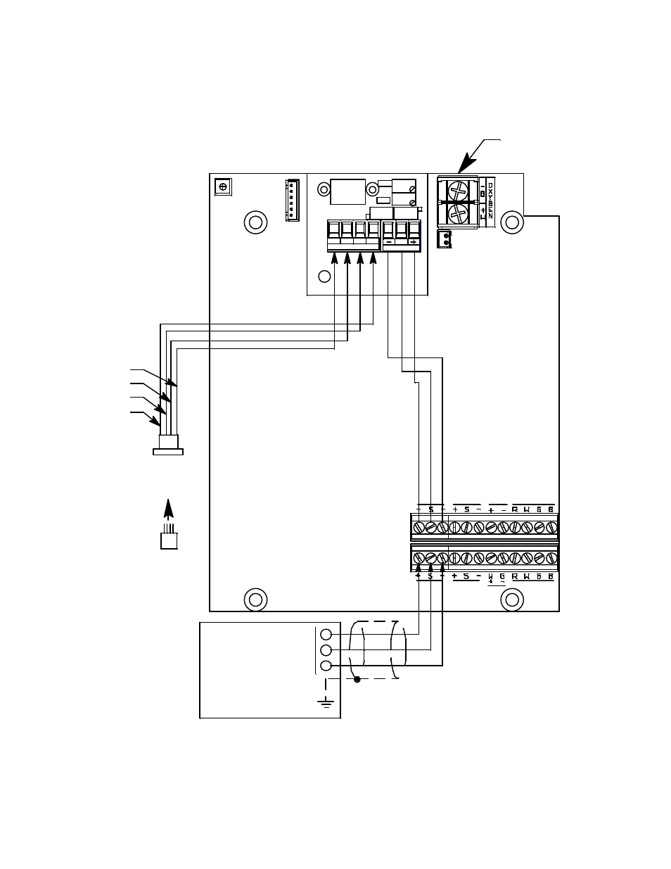
Connect the wires to the applicable detector/transmitter terminal strip at the controller as
shown in Figure 5. Refer to the controller operator’s manual and the controller detector head
specification sheet for the 35-3001A-05-02 for detector/terminal strip connections specific to
the controller.
Figure 5: Wiring the Sample-Draw Detector to a Controller
9.
If shielded cable is used, connect the cable’s drain wire to an available chassis (earth) ground at
the controller. RKI controllers typically have a ground stud that can be used to ground the
cable’s drain wire.
Not Used on
T his V ersion
Z E RO
S
P WR / SI G
SP AN
OXY
LEL/ IR
Green
Black
Red
W hite
PATS201PATS201
AMP 1
AMP 1
OXY
LEL/ IR
+ 24 VDC
Controll er or
Recording
Dev ice
AMP 2
4/20 S ignal
- (DC G round)
IR C O2
Sensor PCB
AMP 2
PATS101PATS101
S e n s o r
C u r r e n t
1 4 8 m A
IR C O2
Sensor
W
LEL
G
B
R