Installation – RKI Instruments 49-8104RK User Manual
Page 5
49-8104RK Standby Battery • 5
Installation
This section describes procedures to mount the standby battery and wire it to a controller.
Installing the Batteries
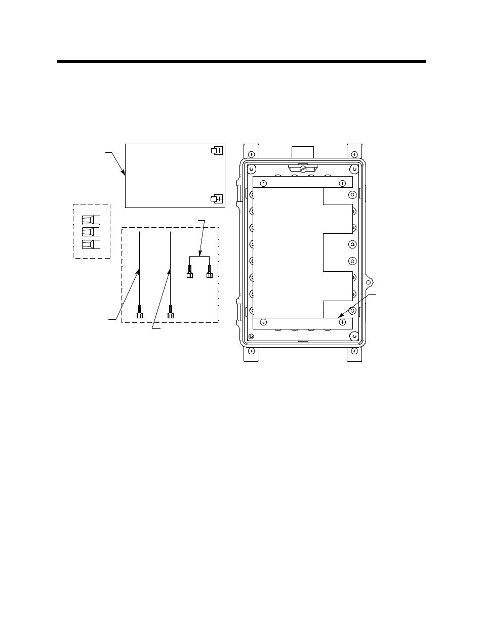
The batteries are shipped separately in order to prevent damage to the housing. Three
wires are provided in a bag in order to make connections to the batteries. The figure below
shows how the standby battery is shipped.
Figure 2: Standby Battery Components as Shipped
1.
Place the enclosure on a table or bench top and open the door.
2.
Unscrew the four screws retaining the battery mounting bracket to the case.
3.
Carefully remove the battery mounting bracket from the case.
4.
Place the batteries in the enclosure and arrange them so that all battery terminals are
on the right as shown in Figure 1.
5.
Place the battery bracket over the batteries and line up the mounting holes in the
bracket with the mounting holes in the case.
6.
Install the four screws that retain the battery bracket and tighten firmly.
7.
Install the positive (red) wire to the “+” connection on the bottom battery (see
Figure 1). This wire is one of three wires in a small bag included with the shipping
contents.
8.
Install the negative (black) wire to the “-” connection of the top battery (see Figure 1).
This wire is one of three wires in a small bag included with the shipping contents.
Battery
Mounting
Bracket
Note: Front
View Shown
W ithout D oor
Jumper Wire
12 Amp Hour
Battery, 2X
Wire (red)
for positive
connection
Wire (black) for
negative
connection
Wire nuts, 3
shipped with unit
(1 extra)