RKI Instruments Beacon 200 User Manual
Page 18
18 • Mounting the Beacon 200 Gas Monitor
115V~
(220V~ Optional)
BAT
CH1-A1
COM-A1
COM-FAIL
COM-A2
+
Channel 1 Recorder
1K Max Impedance
CH2-A1
CH1-A2
BUZ
Reset Switch
(Factory Wired)
Buzzer
(Factory Wired)
Green
AMP/PREAMP
+
S
OXYGEN
+
NO NC
C
NO NC
C
NO NC
C
NO NC
C
NO NC
C
CHANNEL 2
+
OXYGEN
AMP/PREAMP
+
S
BAT +
CH1
OUT
Neutral
Ground
Line (Hot)
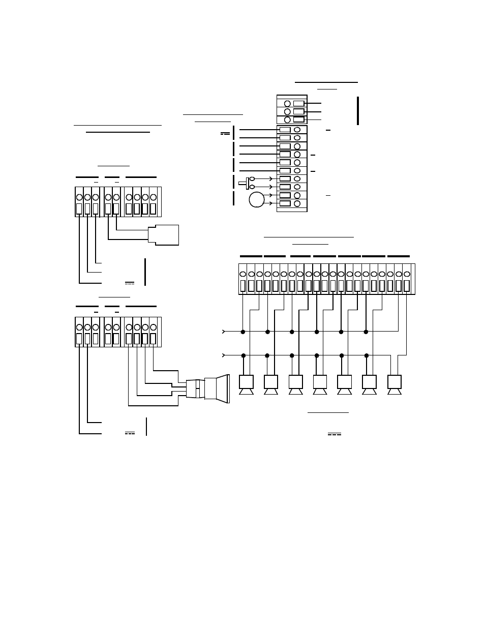
AC In Terminal Strip
Wiring
Black
LEL Detector
R W
G
B
LEL
White
Typical Detector/Transmitter
Terminal Strip Wiring
Only one detector or transmitter
can be
wired to Ch1 or Ch2 at a time. See
detector head wiring diagram for
specific wiring.
CH2-A2
RESET
RESET
BUZ +
Typical Alarm Relay Terminal
Strip Wiring
FB (4-20 mA)
- DC GROUND
3-Wire 4-20 ma
Transmitter
R W
G
B
LEL
+ 24 V
Alarm Devices
NO NC
C
CHANNEL 1
Channel 2 Recorder
1K Max Impedance
CH2
OUT
+
Green
White
Red
+ 24 V
2-Wire 4-20 ma
Transmitter
FB (4-20 mA)
NO NC
C
24 V
Controller Terminal
Strip Wiring
4- 20mA Out
4- 20mA Out
Contact Rating of 10 Amps at
115/220 V~ Resistive or
10A @ 30V Resistive for
Each Set of Alarm Relay
Contacts.
Oxygen
Detector
ALARM
DEVICE
POWER
Figure 5. Beacon 200 Gas Monitor General External Wiring Diagram