Pr eliminar y, Page 29 – Practical Instrument Electronics 850 User Manual
Page 31
Page 29
Pr
eliminar
y
RTD Source
Choose this function to provide a simulated RTD signal into
controllers, temperature transmitters, indicators or any input
devices that measure RTD sensors.
Move the power switch
w
to SOURCE then Double Click the
EZ-DIAL knob to get into the Menu. Turn the knob to scroll
through the settings and press the knob to make your selection.
Select RTD for the FUNCTION, °F or °C for the UNITS and RTD
(Choose from one of Platinum 100Ω, or 1000Ω, Copper 10Ω or
50Ω, Nickel 120Ω or 110Ω curves). Note: Pt 100Ω 3850 is the
most common RTD type.
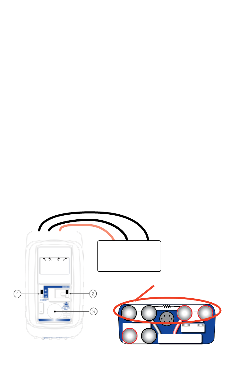
Disconnect all sensor wires from the devices to be calibrated
and connect the PIE 850 to the inputs of the device using 2, 3
or 4 wires.
Instantly output your SPAN and ZERO output settings by moving
the EZ-CHECK switch between HI and LO. You may also select
any third output setting (such as mid-range) using the SET
position on the EZ-CHECK switch. The output is adjusted in 0.1°
increments by turning the knob
e
. Press and turn the knob for
faster dialing with 10.0° increments.
T/C
All mA∙ Read V
-
2
3
RTD
Ω
RTD
Ω
6
5
4
+
Source & Read Hz∙ mV
Source V∙ pH
-
+
1
-
2, 3 & 4 Wire RTD Connections
Instrument with RTD Input
Controller
Temperature Transmitter
Temperature Indicator
Temperature Trip or Alarm
HI
830.0
°C
2 1
+
-
+
3 RTD 4
-
Pt 100
α
=3850