Source mode, Auto stepping in source mode, Rtd connection diagrams, (wire lead kit supplied) – Practical Instrument Electronics 525 Rev B User Manual
Page 3: Model 525 operating instructions
Model 525 Operating Instructions
82 E. Main Street Suite 3.14 · Webster, NY 14580
Tel: 585-872-9350 · Fax: 585-872-2638
[email protected] · http://www.piecal.com/
Practical Instrument Electronics, Inc. Copyright ã 2011. All rights reserved.
525-9002 7/13/11
3-8
Source Mode
Slide the SIMULATE/OFF/READ switch to SIMULATE for direct RTD or T/C output. The Model 525 outputs resistance corresponding to
temperature for the selected RTD or outputs mV corresponding to temperature for the selected T/C type.
Turn the EZ-Dial™ Knob to change temperature, push and turn for faster dialing.
Slide the EZ-Check™ Switch to HI or LO to recall stored settings. While in the HI or LO position, dial a new setting and press the
EZ-Dial™ Knob to store. The DIAL position always holds the last setting dialed there. Using the STORED Values gives you very
accurate values for repeatability. Adjusting the EZ-Dial™ Knob you can check for controller actions, trip points or hysteresis.
Double-click the EZ-Dial™ Knob to return to the configuration menu.
Auto Stepping in Source Mode
Select the step size by pressing the EZ-Dial™ Knob to find the desired step size or %. Select the step time by pressing the EZ-Dial™
Knob to find the desired step time indicated in seconds.
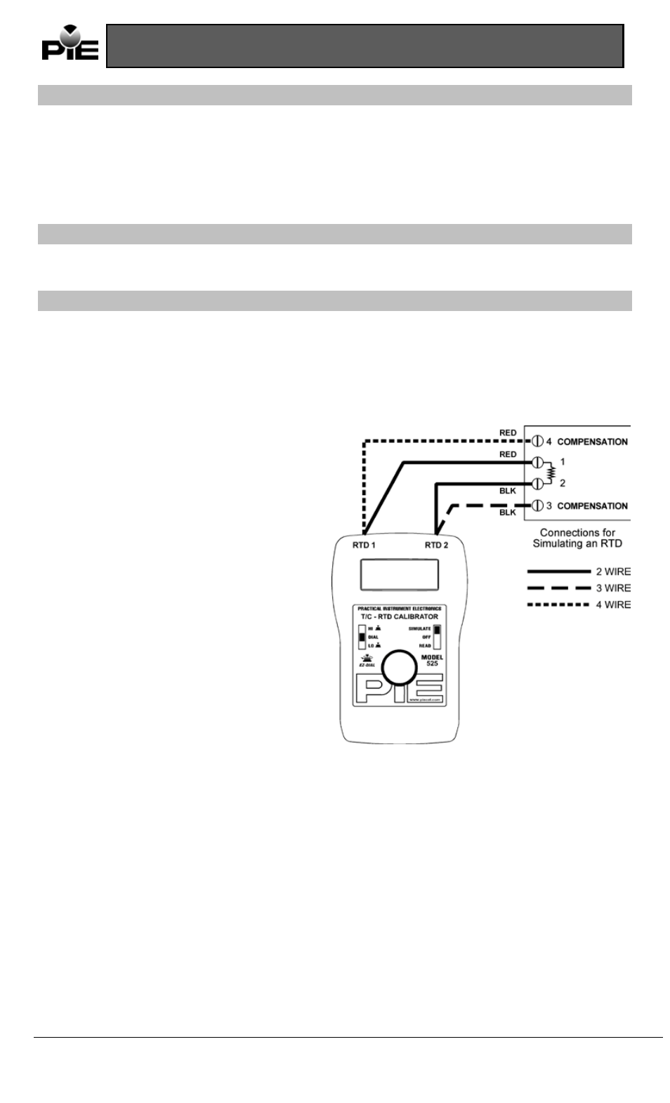
RTD Connection Diagrams, (wire lead kit supplied)
SOURCE ONLY: (See opposite figure)
To connect to a 2 wire transmitter connect one red lead to
post 1 (RTD1) and connect one black lead to post 2 (RTD2).
To connect to a 3 wire transmitter connect one red lead to
post 1 (RTD1) and connect two black leads to post 2 (RTD2).
To connect to a 4 wire transmitter connect two red leads to
post 1 (RTD1) and connect two black leads to post 2 (RTD2).
NOTE:
3 WIRE & 4 WIRE TERMINALS ARE FOR READ MODE
ONLY. See figure page 2.