Practical instrument electronics, Using ground leak detection, Setting up ground leak detection – Practical Instrument Electronics 334Plus User Manual
Page 8: Typical error conditions
Practical Instrument Electronics
82 East Main Street Suite 3.14 • Webster, NY 14580 Tel: 585.872.9350 • Fax: 585.872.2638 • [email protected] • www.piecal.com
Page 8
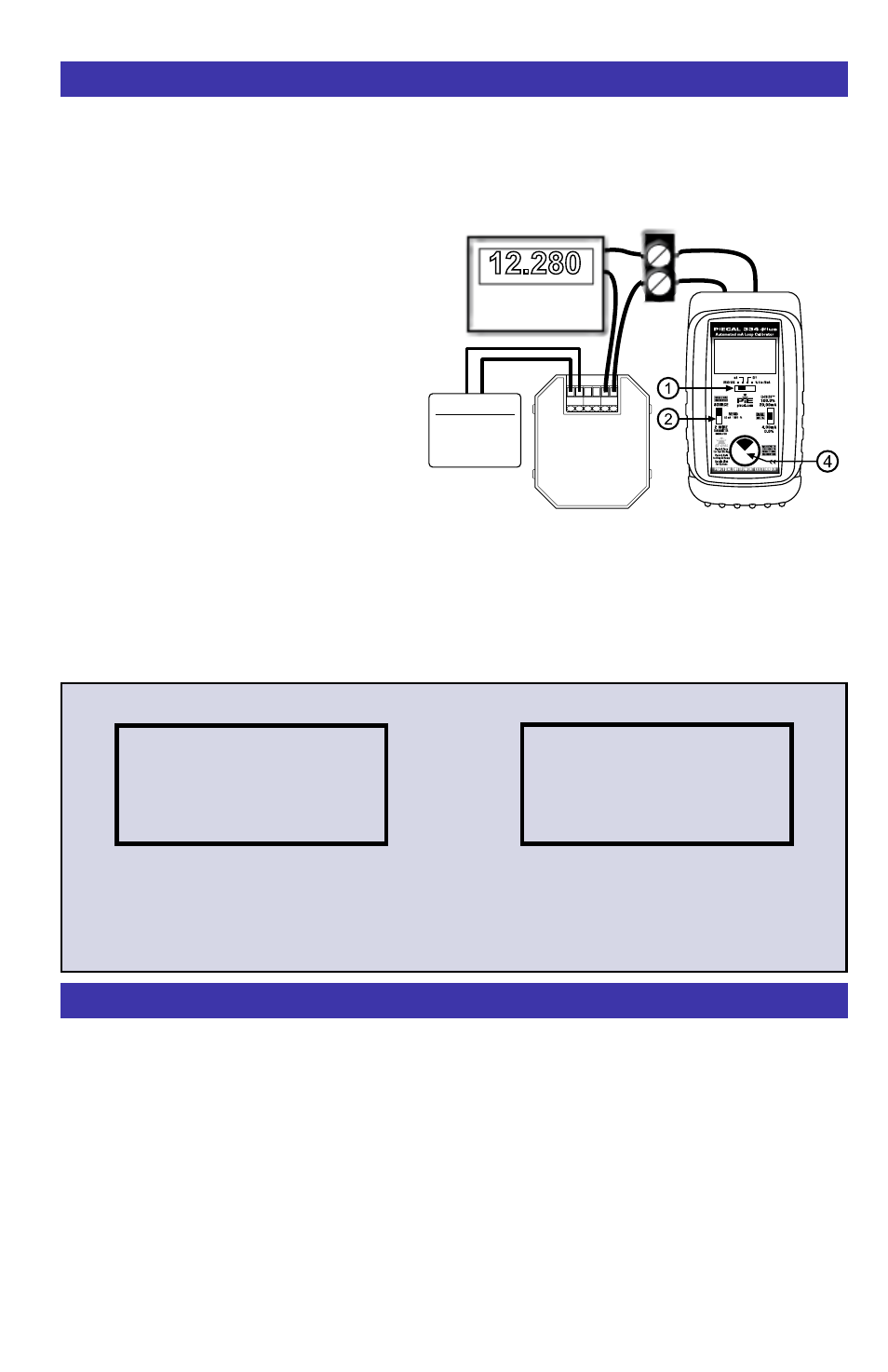
The PIECAL 334Plus is supplying the loop
voltage. There is an control loop error. This
may be a transmitter (set for upscale burnout)
with a bad or missing sensor, or a short in the
loop.
The PIECAL 334Plus is supplying the loop
voltage. A calibrated transmitter is limiting the
loop current to 12.00 mA. An additional 0.28
mA is not controlled by the transmitter and is
leaking somewhere in the loop.
mA OUT, % OUT (Percent of 4 to 20 mA)
Find current leaks in loops caused by ground faults, moisture or corrosion. The 334Plus
simultaneously supplies power to a 2 Wire Transmitter (or loop with a transmitter) while displaying
the 4 to 20 mA output and the amount of current leaking in the loop.
1) Disconnect one or both input wires from
the device to be calibrated.
2) Select
“mA” or “% 4 to 20mA” with
slide switch
q
.
3) Select
“SOURCE” using slide switch
w
.
4) Turn the knob
r
clockwise several
times until full scale output (>24.000
mA/125.00%) The display will indicate
“FULL SCALE” and “LEAKAGE:”
5) Connect the red source lead of the
PIECAL 334Plus to the plus (+) input of
the device and the black source lead to
the minus (-).
The PIECAL 334Plus supplies a nominal 24 volts DC at 24 mA to the 2 Wire Transmitter or loop. The
current passed by the transmitter will be accurately displayed by the PIECAL 334Plus along with an
indication of leakage current at the bottom of the display. If there is an uncontrolled loop, a transmitter
with upscale burnout and bad or missing sensor or a short the 334Plus displays “iLOOP > 24mA”
Note: Many installed transmitters will normally indicate 0.01 to 0.10 mA leakage without significant
control problem. Unstable readings may indicate loose connections or the presence of moisture.
Using Ground Leak Detection
Typical
2-Wire
Transmitter
+ IN - REF +OUT-
Transmitter Input
Sensor
Process Signal
Simulated Input
12.280
FULL SCALE OUT
LEAKAGE: 00.28mA
mA
12.280
PROCESS
INDICATOR
FULL SCALE OUT
24.179
mA
i
LOOP > 24mA
FULL SCALE OUT
12.280
mA
LEAKAGE: 00.28mA
Enabling Ground Leak Detection
Double click the
r
DIAL KNOB at any time the unit is on and the following display will appear for 30
seconds:
Turn the
r
DIAL KNOB to move through the menu. Press the
r
DIAL KNOB to toggle between OFF
and ON or to change the steps setting. These settings are remembered even with the power off.
EXIT MENU - exits this menu immediately and saves any changes. Menu will automatically exit after
30 seconds of inactivity.
GROUND LEAK DETECTION - when ON the 334Plus has the ability to check for current leaks
caused by ground faults, moisture or corrosion that bypass the current control element or transmitter.
Setting Up Ground Leak Detection
Typical Error Conditions