B-control audio bca2000, Control elements and connections – Behringer BCA2000 User Manual
Page 8
8
B-CONTROL AUDIO BCA2000
3. CONTROL ELEMENTS AND CONNECTIONS
The various control elements of your BCA2000 are described in this chapter. All controls and connections are explained in detail,
and there are several useful tips on their use.
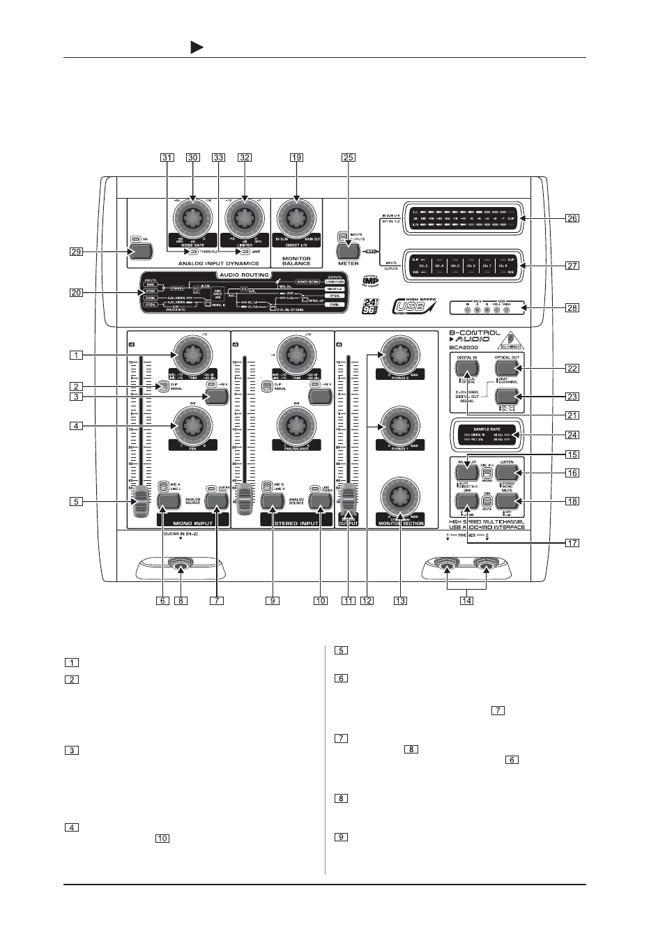
3.1 Control surface
Fig. 3.1: The BCA2000s control elements
3.1.1 Input section
The TRIM control adjusts the level of input signals.
The CLIP and SIGNAL LEDs show the input signal level.
SIGNAL illuminates when there is an incoming signal,
whereas CLIP illuminates when the level is too high and
could cause distortion. If this happens, turn the TRIM control
counterclockwise slightly und the CLIP LED no longer
illuminates.
The +48 V button activates phantom power for a condenser
microphone connected to the XLR input.
+
Be sure to mute your audio system before you
activate the phantom power supply to prevent
audible and potentially damaging switch-on thumps
from reaching your monitor speakers.
PAN positions the signal in the stereo field. If the LINE
STEREO button
is pressed, the PAN control adjusts
the BALANCE between L and R signals in the stereo input
channel.
The 100-mm channel faders control the level of the input
signal that is routed to the A/D converter.
MIC A and LINE L are the two possible positions of this
switch, which controls the input that is routed to a particular
channel. The corresponding LEDs indicate the input you
selected. If GUITAR HI-Z switch
is pressed, the left
MIC A/LINE L switch is deactivated.
The GUITAR (HI-Z) button feeds the guitar signal from the
guitar input
into the mono input channel. This button
overrides the MIC A/LINE L button
: when GUITAR
(HI-Z) is activated, MIC A or LINE L can no longer be
selected.
The GUITAR IN (HI-Z) input allows you to directly connect
an electric guitar or other high-impedance signal
(e.g. passive pickups of acoustic instruments).
MIC B/LINE R is the input selection button for the stereo
input channel. Select between MIC B and LINE R (the right
line input). The corresponding LEDs indicate the selected
input.
3. CONTROL ELEMENTS AND CONNECTIONS