Caution, Sv-series vibrator motor — maintenance – Multiquip SV-SERIES User Manual
Page 14
PAGE 14 — SV-SERIES VIBRATOR MOTOR— PARTS & OPERATION MANUAL — REV. #2 (09/16/02)
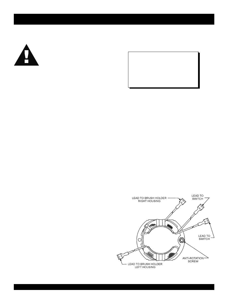
Field Orientation (Figure 5) (when viewed from the rear of
the motor)
MAINTENANCE
CAUTION!
CAUTION!
CAUTION!
CAUTION!
CAUTION!
This is a universal motor and it will run at approximately its rated
speed if the motor and its attached equipment are properly
operated and maintained.
SV-SERIES VIBRATOR MOTOR — MAINTENANCE
Before performing any maintenace on this unit,
ALWAYS MAKE CERTAIN that the switch is
in the "OFF" position and the power cord is
disconnected from the power source.
1.
Have repair work performed by an authorized service
facility, using identical or manufacturer approved
replacement parts.
2.
This motor uses sealed bearings and does not require
lubrication.
3.
Visually inspect the motor daily before use for defective or
missing parts, and have repairs made before use.
4.
Inspect brushes frequently and replace when they become
worn to a length of 3/8".
5.
Keep air inlet and air exit louvers clean and free of concrete
and debris. Failure to do so will result in rapid motor
overheating and parts failure.
6.
Clean air filter as needed. If unit is used in high dust areas,
filter will have to be cleaned more often.
7.
Use wrench to tighten brush caps. The brush cap must be
tight enough that the brush holder does not move.
8.
Should complete disassembly of the motor become
necessary, it will be much easier if all internal components
are built into (Left) housing half P/N 29944-302. Using the
exploded view as a guide, place the anti-rotation pin side
of the field into the slot provided in the -302 housing. See
the end of the maintenance section for proper field
orientation. This anti-rotation pin along with the armature
bearing housings will help align the entire motor. Next,
place (Right) housing half P/N 29944-301 down on top of
the -302 half and snap them together, (the lip around the
housing should "pop" as it aligns). Holding the assembled
halves tightly, flip the entire unit over so that the screws can
be inserted.
9.
The 382V flexible shaft requires cleaning and relubrication
every 100 hours of operation. Refer to 382V flexible shafting
operating instructions for maintenance instructions.
10. Vibrator heads should be inspected and relubricated every
100 hours of operation. Follow the instructions for vibrator
heads.
NOTE
Specification and part number
are subject to change without
notice.
Heat should be used to break down the loctite
while you unthread the head from the shaft.
This will prevent possible damage to the
threads from the loctite.
1.
The field should be positioned so the wires coming out of
the field are have 3 wires coming out of the upper field
shoe and one wire coming out of the lower field shoe.
2.
The 2 long leads from the upper shoe should be routed
through the housing to the switch.
3.
The third shorter lead from the upper shoe should be
connected to the right-hand brush holder when viewed
from the rear of the motor.
4.
The single lead from the lower shoe should be connected
to the left -hand brush holder when viewed from the rear of
the motor.
5.
After assembling complete motor, check the direction of
shaft rotation. When viewed from the front or drive end of
the motor the shaft should turn in a counter-clockwise
direction.
Figure 5. Field Orientation