Components – Multiquip MB25A User Manual
Page 9
MB25A REBAR BENDER • OPERATION AND PARTS MANUAL — REV. #3 (11/18/08) — PAGE 9
COMPONENTS
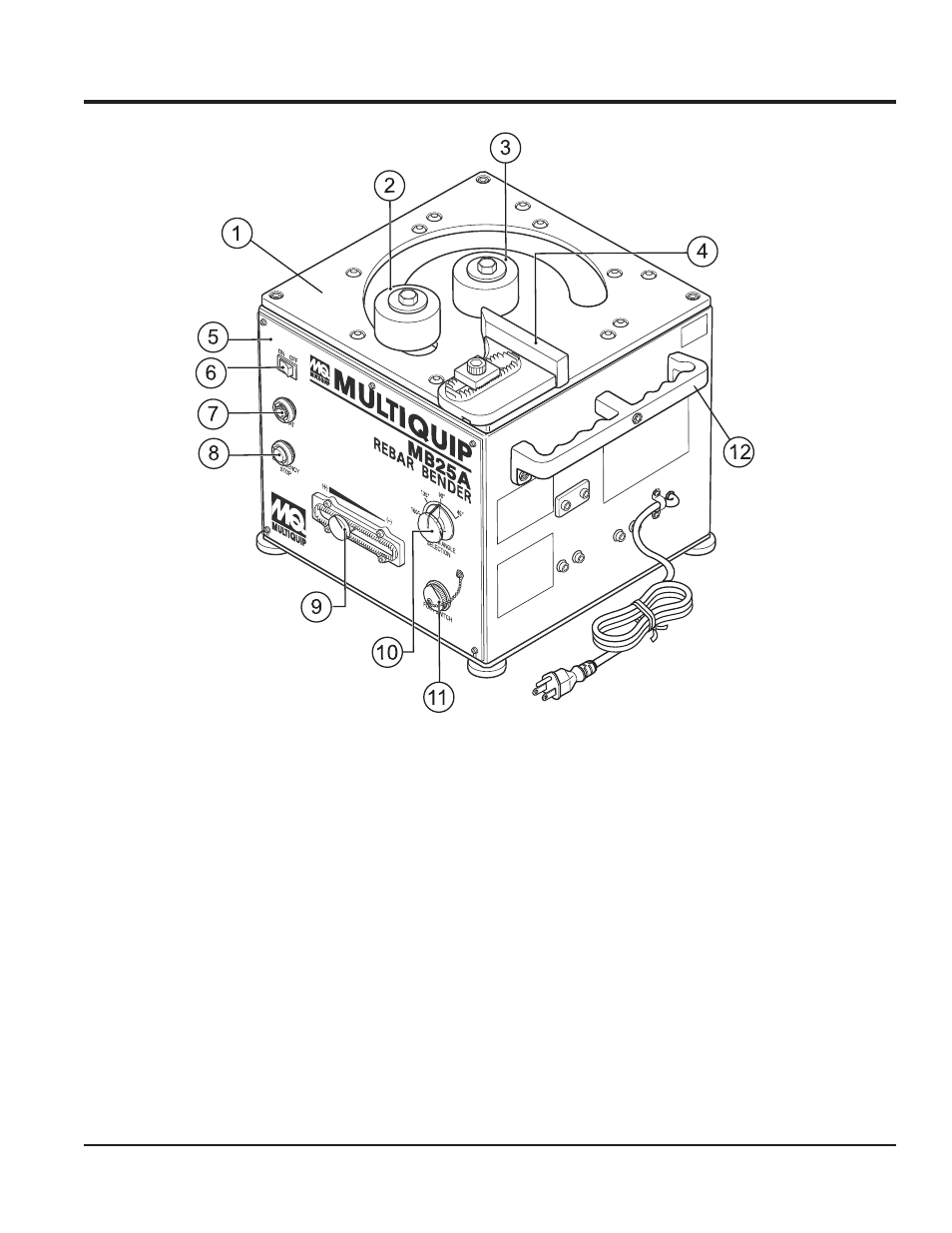
Figure 1. MB25A Components
Figure 1 shows the components of the MB25A Rebar
Bender. These components are described below.
1. Table - Holds the roller, collar, stopper and the rebar
to be bended.
2. Roller - Works in combination with the collar depending
on the diameter of the rebar to bend.
3. Collar -Works in combination with the roller depending
on the diameter of the rebar to bend.
4. Stopper - Holds the rebar in place when bending.
5. Panel A - Holds the different controls for the rebar
bender.
6. Power Switch - Turns the power of the rebar bender
on or off.
7. Start Switch - Starts the bending process.
8. Emergency Stop Switch - Stops the rebar bending
and moves the roller back to the starting position.
9. Angle Adjusting Knob - Used to "fine tune" the angle
after trial bends of a few pieces of rebar.
10. Angle Select Dial - Sets the angle that the rebar is
going to be bent.
11. Connector (for foot switch) - Connects to the foot
switch to start the machine with a push of the pedal.
12. Handle - Used to lift the rebar bender.