Maintenance, Spider removal – Multiquip BS46HLE User Manual
Page 33
BS46H SeRIeS WaLK-BeHIND TROWeL • OpeRaTION aND paRTS maNUaL — Rev. #2 (10/15/13) — page 33
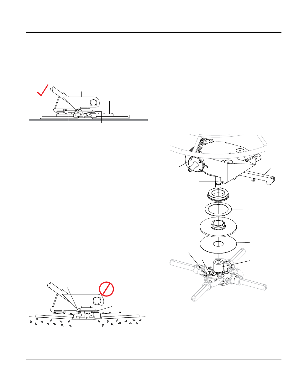
2. Pitch the blades as flat as possible. The pitch
adjustment bolts (Figure 49) should all barely make
contact (0.10 inch max. clearance) with the
lower wear
plate on the spider. All pitch alignment bolts should
be spaced the same distance from the lower wear plate.
If one is not making contact, adjustment will be
necessary.
Figure 49. Correct Blade Pitch (Flat)
3. Adjust the “
high” bolts down to the level of the one that
is not touching, or adjust the “
low” bolt up to the level
of the higher ones. If possible, adjust the low bolt up
to the level of the rest of the bolts. This is the fastest
way, but may not always work. Verify after adjustment
the blades pitch correctly.
4. Blades that are incorrectly adjusted often will not be
able to pitch flat. This can occur if the adjusting bolts
are raised too high. Conversely, adjusting bolts that
are too low will not allow the blades to be pitched high
enough for finishing operations.
5. If, after making blade pitch adjustments the machine
is still finishing poorly, blades, trowel arms, and trowel
arm bushings may be suspect and should be looked
at for adjustment, wear, or damage.
6. Figure 50 illustrates, "incorrect alignment", worn spider
bushings or bent trowel arms.
Figure 50. Incorrect Spider Plate Alignment
GEARBOX
TROWEL
ARM
MOUNTING
BAR
BLADE
STEEL TEST
SURFACE
LOWER
WEAR PLATE
PITCH
ADJUSTMENT
BOLT
NO
“DISHED” EFFECT ON
FINISHED CONCRETE
PITCH
ADJUSTMENT
BOLT
LOWER
WEAR PLATE
maintenance
SpIDeR RemOvaL
Remove the spider assembly from the gearbox shaft as
follows:
1. Locate the cone point square head set screw
(Figure 51) and attached jam nut found on the side of
the spider assembly.
2. Loosen the jam nut and cone point square head set
screw.
3. Carefully lift the upper trowel/gearbox assembly off of
the spider assembly. A slight tap with a rubber mallet
may be necessary to dislodge the spider from the main
shaft of the gearbox.
Figure 51. Spider Removal
GEARBOX
GEARBOX
SHAFT
THRUST COLLAR
BEARING
THRUST COLLAR
W/BUSHING
WEAR RING
LOWER WEAR
PLATE
SPIDER PLATE
JAM
NUT
SET SCREW
(CONE POINT SQ.HD.)
YOKE ARM