Assembly and installation – Multiquip B46-SERIES User Manual
Page 21
B-46 WALK-BEHIND TROWEL • OPERATION AND PARTS MANUAL — REV. #8 (05/08/12) — PAGE 21
F
IN
IS
H
FINISH
J
C
O
M
B
O
COMBO
P
R
E
L
O
A
D
T
R
IM
IN
D
IC
A
TO
R
PRELOAD
TRIM
INDICA
TO
R
F
IN
IS
H
FINISH
B
C
O
M
B
O
COMBO
1
3
4
2
6
5
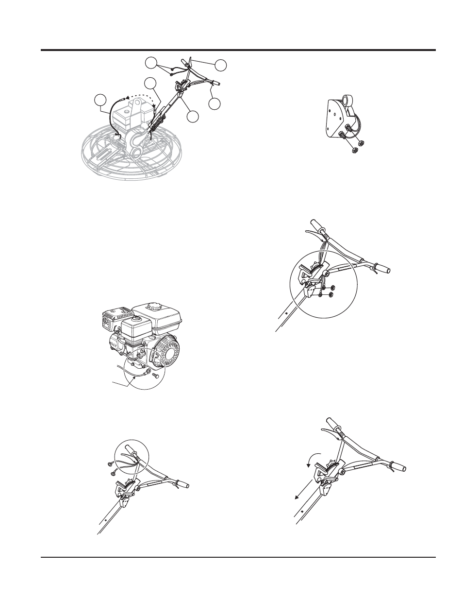
Ground Wire
from handle
6.
Connect the two wires from the Operator Presence Lever
to the Safety Stop Switch terminal lugs. (one per lug; either
position). Re-install and tighten the nuts. (Figure 14).
Figure 14. Wiring Connection
3.
Install the ground wire to the engine, (Honda engine shown,
Figure 11).
Figure 11. Ground Wire Connection
4.
If so equipped, re-position the Operator Presence Lever
on the handlebars, (Figure 12).
Figure 12. Repositioning the Lever
5.
Remove one 7mm nut from each of the terminals on the
Safety Stop Switch. (Leave the existing two wires to the
switch connected.) (Figure 13).
Figure 13. Safety Stop Switch Connection
Figure 10. Safety Wire Connection
1.
Expose the pitch cable to maximum by adjusting the handle
pitch to the "no pitch" position. Pivot the pitch handle forward
or no pitch, (Figure 15).
Pitch Cable Installation
Figure 15. "No Pitch" Position
ASSEMBLY AND INSTALLATION
NO PITCH
FORWARD
1
Operator Presence Wiring (Option)
2
Operator Presence Lever (Option)
(Temporary Positioning for Shipping)
3
Tail Wire From Engine
4
Safety Stop Wire From Switch
5
Safety Stop Switch
6
Throttle Lever