C-30hdn pump — control box components – Multiquip C30HDN User Manual
Page 18
PAGE 18 — C-30HDN PUMP — OPERATION AND PARTS MANUAL — REV. #11 (03/29/12)
C-30HDN PUMP — CONTROL BOX COMPONENTS
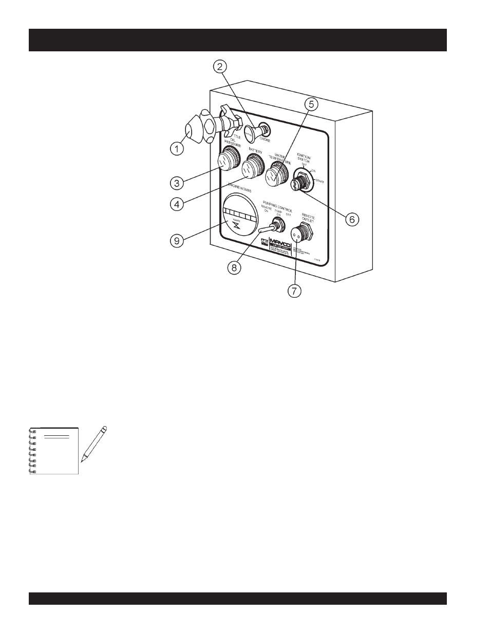
Figure 5. Pump Control Box Components
1.
Throttle Control Knob – This is a variable speed type
control. Turning the throttle lock (CCW) left unlocks the
throttle allowing the throttle control cable to be pulled out to
the desired position. Once the desired throttle position
(speed) has been achieved, turning the throttle lock to the
(CW) right locks it in place. Use the fine tune adjustment
knob to fine tune the engine rpm's.
To place the engine in idle, press the top button inward all
the way.
4.
Battery Charge Indicator Lamp – Indicates if the
electrical system is charging properly. If the "
Battery
Charge
Indicator Lamp
" is lit, this is an indication that the
charging system is malfunctioning.
STOP
the engine and
remedy the electrical charging problem.
5.
Water Temperature Lamp – In the event of high engine
water temperature (220 degrees Fahrenheit), this lamp will
be lit.
STOP
the engine immediately if this lamp comes on.
NEVER
run the engine when this lamp is on.
6.
Ignition Switch – Insert the ignition key here to start the
engine. Turn the key clockwise to the
ON
position, then
continue turning clockwise to the
START
position and
release. To stop the engine turn the key fully counter-
clockwise to the
STOP
position.
7.
Remote Control Input Connector – Insert the remote
control input cable into this connector.
8.
Pumping Control Switch – This 3-position switch controls
the pumping of the pump. The
left most
position is for use
with the remote control unit, the
center
position is for
normal pumping operation, and the
right most
position
(OFF) prevents pumping.
9.
Hourmeter– Display's the number of hours the pump has
been in use.
ALWAYS
unlock the throttle control
before it is pushed in because if this is
not done first, possible damage could
result to the locking mechanism.
Figure 5 illustrates the location of the major
components for the C-30HDN Control Box. The
function of each component is described below:
NOTE
2.
Choke Knob – When the starting of an cold engine is
required, open choke by pulling choke control to extreme
out position. Let engine run for 3-5 minutes, then push choke
knob all the way in (close position).
3.
Oil Pressure Indicator Lamp – In the event of low oil in
the engine crankcase or low oil pressure, the oil "
Oil
Pressure Lamp
" indicator will be lit.
STOP
the engine
immediately if this lamp is lit.
NEVER
run the engine when
this lamp is on.