Sdw-225ss — controls and indicators – Multiquip SDW225SS User Manual
Page 18
PAGE 18 —SDW-225SS WELDER/GENERATOR— OPERATION & PARTS MANUAL — REV. # 2 (10/07/05)
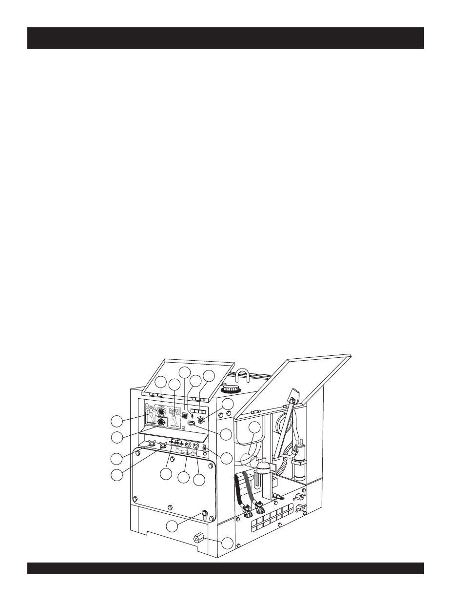
SDW-225SS — CONTROLS AND INDICATORS
17. Fuel Drain Plug – Remove this plug to drain fuel from the
fuel tank.
18. Frame Ground Lug – Connect a ground strap between
this lug and a ground rod. Make sure that the ground rod is
inserted deep into the ground to provide a good earth
ground. Consult with local Electrical and Safety Codes for
proper connection and depth of ground rod.
19. Oil Filter – Provides oil filtering for the engine.
20. Hour Meter – Indicates number of hours machine has
been in use or hours engine was run.
21. Current Control (CC) Adjustment Knob – Use this
control to adjust the welding current between 50 to 225
amps. This function will not work in the CV mode.
22. Voltage Control (CV) Adjustment Knob – Use this
control to adjust the welding voltage between 15 to 28 V.
This function will not work in the CC mode.
23. Welding Type (Wire/Stick) Selector Switch (CV/CC) –
Turn this selector switch toeither CV or CC for welding.
DO NOT turn this switch under load.
24. Current Range Selector Switch (CC) – Turn this selector
switch to either low or high for welding. DO NOT turn this
switch under load.
25. Main Circuit Breaker – This 2-pole circuit breaker provides
circuit protection (250V @25 amps) for the Electric Parts
Assembly.
26. Circuit Protector Circuit Breaker – This single pole circuit
breaker provides circuit protection (120V @20 amps) for
the G.F.C.I receptacle.
z Low Oil Pressure Lamp - lights to indicate that
the engine pressure has fallen below acceptable
level.
z High Water Temperature Lamp - lights to indicate
that the water temperature has exceeded 239
°F.
z Electrical System Lamp - lights when the electrical
system is not charging properly.
z Pre-heat Lamp- when the key switch is set to the
pre-heat position, this lamp turns on. When the lamp
turns off, the key switch can be turned to the start
position.
29. Ignition Switch – With key inserted, turn clockwise to
start engine.
30. Positive Welding Output Terminal – Connect the
welding cable to this terminal. Select the appropriate
polarities according to the application. See Table 7.
31. Negative Welding Output Terminal – Connect the
negative cable of the welding source to this terminal. Select
the appropriate polarities according to the application. See
Table 7.
32. Receptacle G.F.C.I. – This receptacle provides 120 volts
output at 20 amps.
33. Receptacle – Provides 120 volts output at 25 amps.
34. Receptacle – Provides 120/240 volts output at 25 amps.
Figure 3. SDW-225SS Components 2
27. Idle Control Switch – Regulates the engine speed when
the generator is under load.
28. Warning Lamp Display – Includes the following lamps.
MQ POWER
WHISPERWELD
SDW-225SS
STARTER SWITCH
RUN
HEAT
START
STOP
AC CIRCUIT
BREAKER
IDLE CONTROL
ON
OFF
0
0
0
0
0
HOURS
HOUR METER
MQ POWER
WELDER
/ GENERA
TOR
D25200000
19
28
27
25
24
21
20
29
17
26
32
34
33
18
23
22
30
31