C: installing the capacity monitor faucet – Purenex Multipure Aquaversa User Manual
Page 12
12
3.2-c: Installing the Capacity Monitor Faucet
(continued)
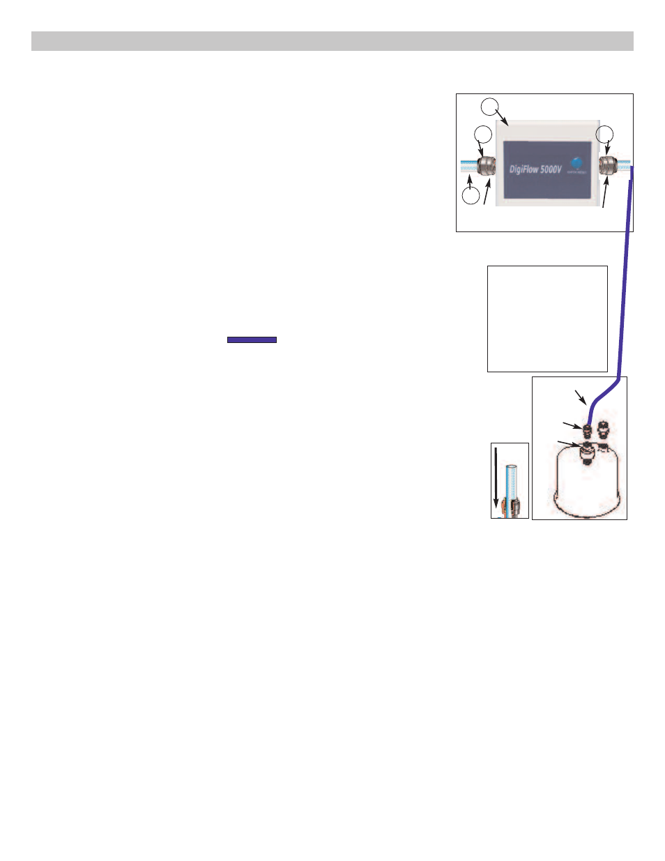
Connect the Tubing to the Filter Monitor Unit
nOTe: Complete this step only after the Dws tubing has been connected in
section 3.4: Connect the Tubing to the Housing.
1.
Connect the two tube fittings (#15) (MC744) to the Filter Monitor unit (#14)
(FMu) by threading them into the threaded ports, one on each side
(tighten securely, but do not over-tighten).
2.
The FMu can be mounted either horizontally or vertically, but vertical
installation is recommended. nOTe: The FMu will function with water flow
in either direction.
3.
Fully insert the blue plastic tubing (#5) from the Dws OuTleT into one
side of the FMu.
4.
Fully insert the blue plastic tubing (#5) from the faucet into the other
side of the FMu.
nOTe: when pushing the tubing into the fitting, you will encounter some resistance.
This does not mean that the tube is fully inserted. Continue to push firmly until the
tubing is inserted as far as possible (roughly 5/8” into the fitting).
Set up the Filter Monitor Unit
1. Connect the black wire (#8) from the leD Display Plate into the Filter Monitor
unit (#14).
2. Open the top of the FMu and insert two (2) AAA batteries (not included) into the
battery compartment, making sure to match the + and – signs. Close the battery
compartment.
3. There will be a long audio sound, and the leD will blink green for two seconds,
and then blink green five times.
4. After installing the batteries, press the check/reset button to confirm the leD is
functioning.
5. Press and hold the check/reset button on the Filter Monitor unit (FMu) for three
(3) seconds. You should hear a long audible sound.
6. The leD on the leD Display Plate will blink green for one (1) second with an
audible sound, then blink green and red for one (1) second each, and then blink
green five (5) times twice. The remaining capacity and time is now reset to the
original capacity.
7. Peel off the paper backing from the hook-and-loop connector strip, and attach
one piece to the back of the FMu. Peel off the paper backing from the second
hook-and-loop connector strip and attach it to the desired wall location. Attach the
FMu to the wall using the two hook-and-loop connector strips.
5
Capacity Monitor Assembly
Insert blue tubing 5/8”
tubing
Adapter
OuTleT
in
se
rt
Insert tubing and push
until you feel resistance
-- at this point, the
tubing is not fully
inserted. Push firmly
until the tubing is
inserted as far as
it will go.
Pull to check that the
tubing is secure.
15
15
14
OUTLET
to faucet
INLET
from housing