Floor and table loading considerations, Mechanical shock/vibration, Load frame connections – MTS Acumen Electrodynamic User Manual
Page 19: Connecting the main power
Floor and Table Loading Considerations
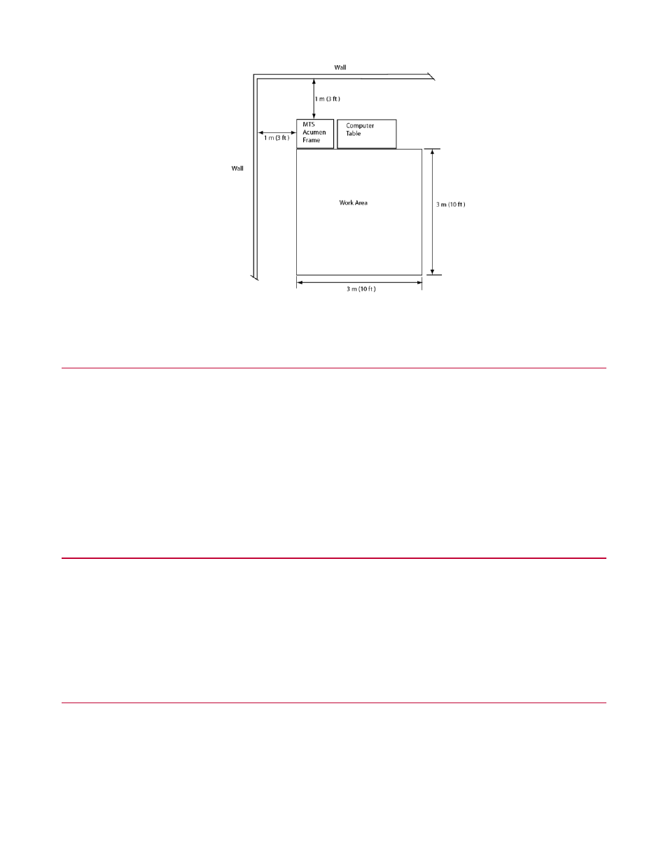
Once the final layout for your system laboratory has been developed, the dimensional and weight information
for the various system components should be supplied to the building facility personnel to ensure that proper
building loading and vibration considerations have been evaluated. If an MTS Acumen load frame table is
not purchased, a table upon which the frame is placed is sturdy, level, and capable of supporting the weight
of the machine. The machine is a dynamic test machine, and therefore requires a table with a robust structure.
A review of the final installation plan by building personnel is recommended to check static and dynamic floor
loading.
Mechanical Shock/Vibration
Where heavy load or high frequency testing is performed, vibration produced by testing can be introduced
into the laboratory floor. In extreme cases, siesmic mass isolation can be used to minimize vibration problems.
Adequate isolation of the load unit is often possible with the supplied rubber pads under the base of the load
frame.
Load Frame Connections
Connecting the Main Power
The input voltage of MTS Acumen 1 frame is single phase 100-120 V /200-240 V, 50-60 Hz.
The input voltage of MTS Acumen 3 frame is single phase 200-240 V, 50-60 Hz.
MTS Acumen™ Electrodynamic Test System 19
Site Preparation