MTS Model 512-01 Hydraulic Power Unit User Manual
Page 14
Model 512.01 Hydraulic Power Unit
14
Installation
1.
Position the hydraulic power unit.
You should determine where to put the hydraulic power unit (HPU).
Since it is connected to the other hydraulic equipment through
hydraulic lines, the HPU can be located remotely.
•
Use the lifting rings (with a crane or fork lift) to move the HPU
unit into place.
•
The HPU must be located where adequate air movement is
available. A clearance of 50 mm (2 ft) is required between the
heat exchanger and a wall.
•
The base of the HPU has four holes to secure the unit in place.
2.
Connect an external Emergency Stop switch.
An optional
Emergency Stop
switch can be connected to the 14 pin
CPC connector located on the control box.
A jumper plug is required if a remote
Emergency Stop
switch is not
installed. The HPU will not run without an
Emergency Stop
switch or
a jumper plug installed.
3.
Connect the electrical service to the HPU.
NOTE
You may want to have an electrician complete this step. Also, local
electrical codes supersede any information found here.
Plug the power cord into a 115 V (ac), 60 Hz, 1 phase outlet rated for
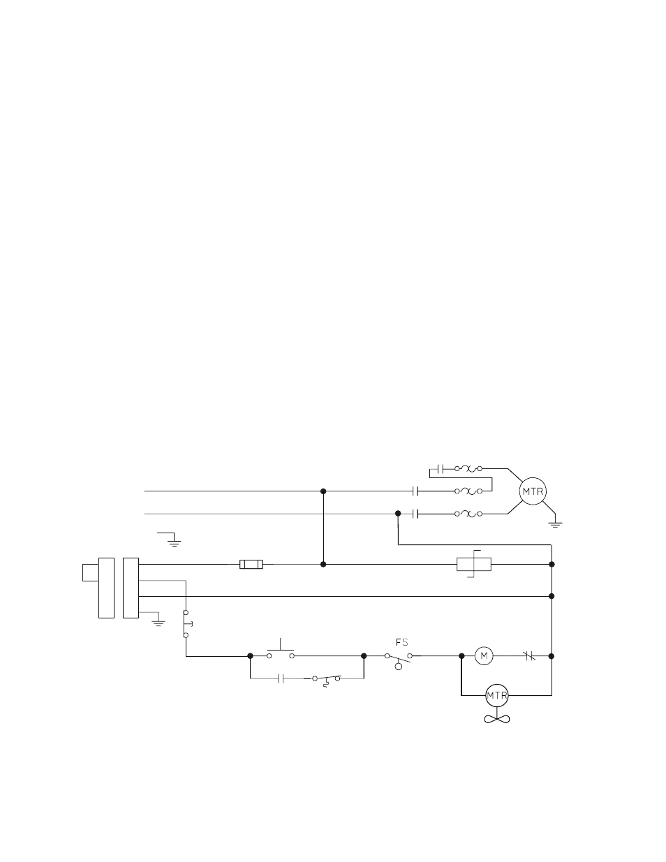
20 A. The electrical schematic is provided if you need to check any
wiring. This unit must be grounded.
Electrical Schematic
Remote
Emergency
Stop Switch
CPC-14S
1 A
L1
L2
Stop Switch
FU1
Start
Switch
Varistor
OL
M–1
SS1
TAS
Opens at
55
°
(130
°
)
Low Fluid
Switch
(opens at
70% full)
Fan and Motor
OL
M
M
M
OL
OL
1
3
8
1
3
8
A Jumper Plug is required
if a Remote Emergency
Stop Switch Not
Connected
Green
9
9