Mag Layers USA GMLB-201209 User Manual
Page 8
MAG.LAYERS
GMLB-201209-R Series
R
R
R
E
E
E
L
L
L
I
I
I
A
A
A
B
B
B
I
I
I
L
L
L
T
T
T
Y
Y
Y
T
T
T
E
E
E
S
S
S
T
T
T
•
Mechanical Performance Test
ITEM
SPECIFICATION
TEST CONDITION
Solderability
More than 90% of the terminal electrode shall
be covered with fresh solder.
Solder: 96.5Sn-3.0Ag-0.5Cu
Solder Temperature: 245
±
5
℃
Flux: Rosin
Dip Time: 3
±
1 Seconds
Soldering Heat Resistance
The chip shall not crack.
More than 75% of the terminal electrode shall
be covered with solder.
Solder: 96.5Sn-3.0Ag-0.5Cu
Solder temperature : 260
±
5
℃
Flux: Rosin
Dip time: 10
±
1 seconds
TYPE
W(KGF)
TIME (SEC)
GMLB-160808
GMLB-201209
0.6
GMLB-321611
1.0
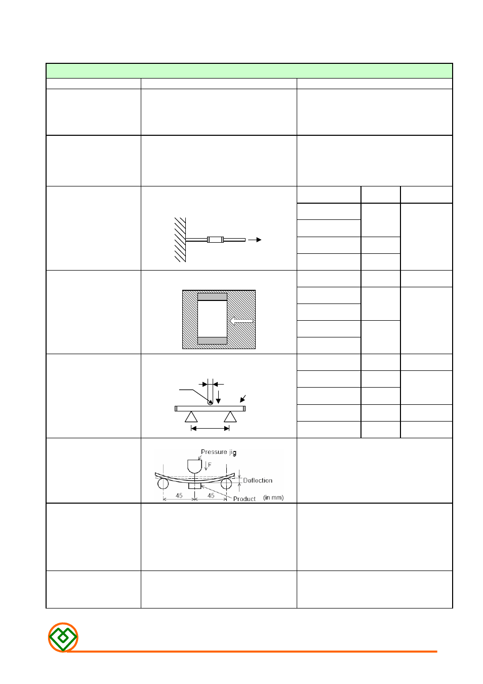
Terminal Strength
The terminal electrode shall not be broken off
nor the ferrite damaged.
W
GMLB-453215
1.5
30
±
5
TYPE
W(KGF)
TIME (SEC)
GMLB-160808
GMLB-201209
1.0
GMLB-321611
Terminal Strength
The terminal electrode shall not be broken off
nor the ferrite damaged.
GMLB-453215
2.0
10
±
5
TYPE
A(MM)
P(KGF)
GMLB-160808
1.0
GMLB-201209
1.4
1.0
GMLB-321611
2.0
2.0
Bending Strength
No mechanical damage.
The ferrite shall not be damaged.
A
Chip
P
1.0
R0.5
GMLB-453215
2.7
2.5
Bending Test
Appearance: No damage
Substrate: PCB(100mm
×
40mm
×
1.6mm)
Solder: Reflow
Speed of Applying Force: 0.5mm / s
Deflection: 2mm
Hold Duration: 30 s
Vibration
Impedance shall be within
±
20% of the initial
value.
There shall be no mechanical damage.
The sample shall be soldered onto the printed
circuit board and when a vibration having an
amplitude of 1.52mm and a frequency of from
10 to 55Hz/1 minute repeated should be
applied to the 3 directions (X,Y,Z) for 2 hours
each.
Drop shock
No apparent damage
Dropped onto printed circuit board from
100cm height three times in x, y, z directions.
The terminals shall be protected.
W