Lowell manufacturing company – Lowell MIX1 User Manual
Page 4
4
REMOVABLE
PHOENI X
CONNECTOR
Lowell Manufacturing Company
100 Integram Drive
Pacific, Missouri 63069 U.S.A.
Call: 800-325-9660
Fax: 636-257-6606
Click: www.lowellmfg.com
Instruction Sheet
IS-MIX1
Issued: 6-1-14
The MIX1
“MAIN” output connection is an RCA phono jack. The connecting output cable should
be wired with the pin “hot” or “+” and with the sleeve “common” or “-”. The main output jack is
fed after the master volume control and low cut filter.
MAIN OUTPUT JACK CONNECTION
Sleeve
_
+
Pin
PHANTOM POWER
The microphone inputs on the MIX1 do not provide phantom power for condenser microphones. An external
phantom power supply (sold by others) may be used to provide phantom power to a condenser microphone before
feeding the signal to the MIX1 microphone input.
Microphones may be connected to the three (3)
screw terminals for the “MIC” input of channel 1 through channel 6.
Note: the input channel chosen will depend on the muting scheme chosen. For example: If the microphone will
have the highest priority and will mute all other channels, connect to the channel 1
“MIC” input and set the “MUTE”
switch to “2-8”. If the microphone will be a lower level priority and will be muted by an input fed to channel 1,
choose the microphone input on channel 2-6.
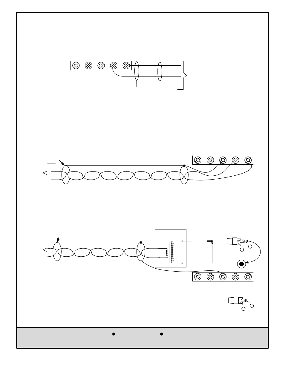
MICROPHONE INPUT WIRING
GND
MIC
+
+
_
_
MIC
CH2
CH1
+
_
Shield
Shield
From
Microphone
If the 600
W balanced page port output is a line level output and is not adjustable, it is best to use the Lowell
TLM-600 matching transformer (or any other 600
W balanced to high impedance unbalanced telephone
transformer adaptor) and feed the telephone page input to the channel 1 Aux input RCA jack (as shown below).
Note: The MIX1 muting priority for channel 1 is still functional when using the Aux input RCA jack to feed the
paging input to channel 1.
From a
600
W
Balanced
Telephone
System
Page-Port
Output
600
W Stranded Twisted-Pair Wiring
Shielded wiring f rom a t elephone page port output would not typically be shielded,
but if shielded wiring is used, wire the feed as shown below:
BUTT SHIELD
(No connection)
DRAIN
SHIELD
GND
MIC
+
+
_
_
CH1
CH2
MIC
600
W
25k
W
Lowell
TLM-600
From a
600
W
Balanced
Telephone
System
Page-Port
Output
600
W Stranded Twisted-Pair Wiring
Shielded wiring f rom a t elephone page port output would
not t ypically be shielded, but if shielded wiring is used,
wire the feed as shown below:
BUTT SHIELD
(No connection)
DRAIN
SHIELD
GND
MIC
+
+
_
_
MIC
CH1
RCA Cord To Plug
Into Aux CH1 Is Not
Included With TLM-600
Sleeve
_
+
Pin
Shield(-)
Center
Conductor (+)
TELEPHONE INPUT WIRING
The page port output from a telephone system will be a 600
W balanced line level output. If the telephone page
port output can be reduced to a microphone level, it is possible to connect the telephone page feed to the
channel 1
“MIC” input of the MIX1 (as shown below) .