Ma30 front panel, Ma30 rear panel, Amplifier installation and connection – Lowell MA30 User Manual
Page 4: Lowell manufacturing company
4
REMOVABLE
PHOENI X
CONNECTOR
Instruction Sheet
IS-MA30
Issued: 9-10-14
Lowell Manufacturing Company
100 Integram Drive
Pacific, Missouri 63069 U.S.A.
Call: 800-325-9660
Fax: 636-257-6606
Click: www.lowellmfg.com
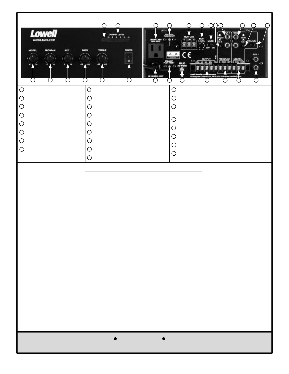
MA30 Front Panel
MA30 Rear Panel
2
3
4
7
8
6
1
9
10
11
12
13
14
15
16
17
18
19
20
22
23
24
25
Amplifier Installation and Connection
This unit was carefully checked and packed before leaving the factory . However, it is always a good idea to inspect
the shipping container and unit for indications of improper handling . If the unit has been damaged, make an
immediate claim to the dealer or distributor from whom it was purchased . If the unit was shipped to you, notify the
transportation company without delay, saving all packing materials, in order to process the claim.
INSPECTION
Before installing the amplifier, continue the inspection by running a quick performance check. Connect an 8
W test
speaker to the 8
W direct output terminals and a tuner, tape deck, or CD player to one of the aux inputs and set the
controls for operation. CAUTION: TO PROTECT THE SPEAKER FROM DAMAGE, DO NOT TURN THE UNIT ON
UNTIL ALL CONNECTIONS HAVE BEEN MADE. IN ADDITION, MAKE SURE THE UNIT IS GROUNDED
BEFORE TESTING. In this way you can check the basic operation of the amplifier before actually installing the unit
and making all of the final terminations required for the permanent installation. If shipping damage has resulted in
the amplifier being inoperable out of the box, call Lowell Customer Service to arrange for a replacement .
INITIAL PERFORMANCE CHECK
GENERAL WIRING AND INSTALLATION GUIDELINES
DO NOT run microphone cables near AC power wires, data cables, telephone cables, or speaker wiring to avoid
picking up extraneous signals in the sound system .
DO NOT run speaker output cables near data cables, telephone cables, or other low voltage wiring that could pick
up the signal from the higher level speaker cables.
DO NOT run high impedance unbalanced wiring more than 20' to avoid picking up noise and affecting the frequency
response of the sound system.
DO use shielded cable for all microphone and line level cables (except the balanced 600 ohm input line from a
telephone system may be twisted pair cable).
DO make sure that all speakers are wired in phase with each other .
DO make sure there are no short circuits on the loudspeaker lines before connecting them to the amplifier output .
Music-On-Hold (MOH) Output (Screw Term)
18
Music-On-Hold (MOH) Level Control
19
Mute Switch (
Switch “ON”, MIC/TEL Input
Mutes AUX 1, AUX 3 & PROGRAM Inputs)
20
Program or Aux 3 Selector Switch
21
Aux 3 Input (RCA Jacks)
22
Aux 2 Input (RCA Jacks)
23
MIC/TEL Input Pad Switch
25
MIC/TEL or Aux 2 Selector Switch
24
Speaker Output (Screw Terminals)
1
2
Program Input (Screw Terminals)
13
MIC/TEL Input (Screw Terminals)
14
AC Line Cord
9
Circuit Breaker for Amplifier
10
Earth Ground Connection Screw
11
Aux 1 Input (RCA Jacks)
1
5
Convenience AC Outlet
16
Circuit Breaker/Convenience Outlet
17
1
MIC/TEL Volume Control
2
PROGRAM Volume Control
3
AUX 1 Volume Control
6
Power Switch
Power Indicator LED
7
Output Level Indicator LED
8
4
Bass Control
5
Treble Control
5
21