1 wiring of motor temperature monitoring, Wiring of motor temperature monitoring, Electrical installation – Lenze EVF9383 User Manual
Page 93: Connection to incremental encoder input (x8)
Electrical installation
Motor connection
Wiring of motor temperature monitoring
l
93
EDKVF9383 DE/EN/FR 4.0
5.5.1
Wiring of motor temperature monitoring
The drive controller features 2 connections for motor temperature monitoring:
ƒ
Terminals T1, T2 for connecting a PTC thermistor or thermal contact (NC contact).
ƒ
Pin X8/5 and X8/8 of the incremental encoder input (X8) for connecting a KTY
thermal sensor.
Incremental encoder input (X8)
Terminals T1, T2
Connectable thermal
sensor
Linear thermal sensor (KTY)
l
PTC thermistor
– PTC thermistor with defined
operating temperature (to
DIN 44081 and DIN 44082)
l
Thermal contact (NC contact)
– Temperature switch as NC contact
Tripping point
l
Warning: Adjustable
l
Error (TRIP): Fixed at 150 °C
l
Fixed, (depending on the PTC/thermal
contact)
l
PTC: R
J
>
1600
W
l
Configurable as warning or error
(TRIP)
Notes
l
Monitoring is not active in the Lenze
setting.
l
The KTY is monitored with regard to
interruption and short circuit.
l
Monitoring is not active in the Lenze
setting.
l
If you do not use a Lenze motor, we
recommend a PTC thermistor up to
150°C.
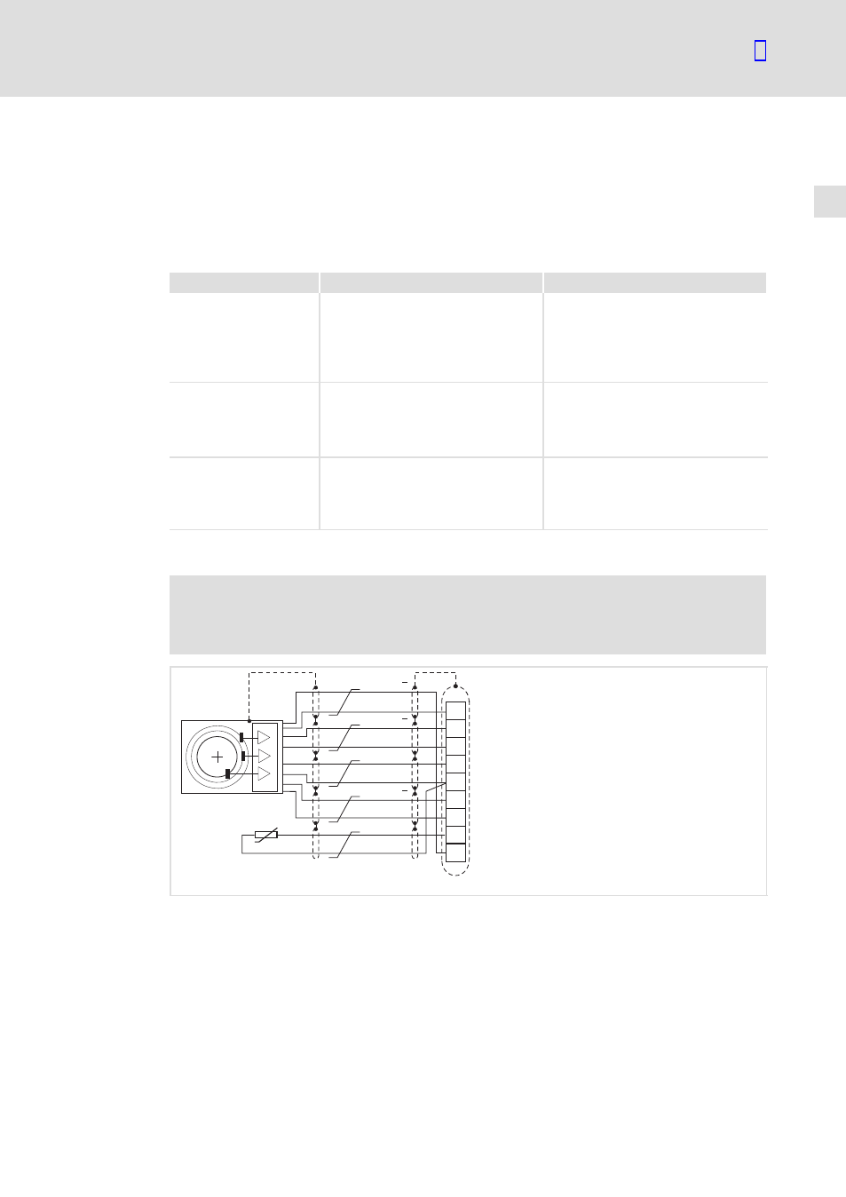
Connection to incremental encoder input (X8)
)
Note!
Lenze system cables for motor feedback include additional cores for
temperature feedback. The cables are designed for wiring according to EMC.
B
V
CC5 _ E
GND
Z
+KTY
-KTY
1
2
3
4
5
6
7
8
9
A
X8
A
B
Z
KTY
9300VEC068
Fig. 5−13
Connection to incremental encoder input (X8)
X8/5, X8/8
Connection of KTY thermal sensor