Lenze Range 7800 User Manual
Page 5
ET46/fa
checked:
19.04.89
~4B 33.0831
GB
page:
4
4.
Installation
instructions
The controller
should be
fitted vertically
with the terminals
located
at
the bottom.
Ensure that there
is
a
free space
of
±:LOOin~
at
the top and bottain,
and 50 mm
at
the sides
in
order
to
inaintain the flow of
air
tI~xrough the heat
sink
and controller.
The
maxrmmm
ambient temperature must not exceed 400C.
In case
of an
earth
circuit fault,
the mains
choke
limits
the current
rise and
improves the ~nains current factor.
The 7800
inverter series
inust only be operated with specif led mains
choke
and sexni-conductor
fuses
(see paint
10./il.).
5.
Connectinc~
instructions
5..l External
set—value
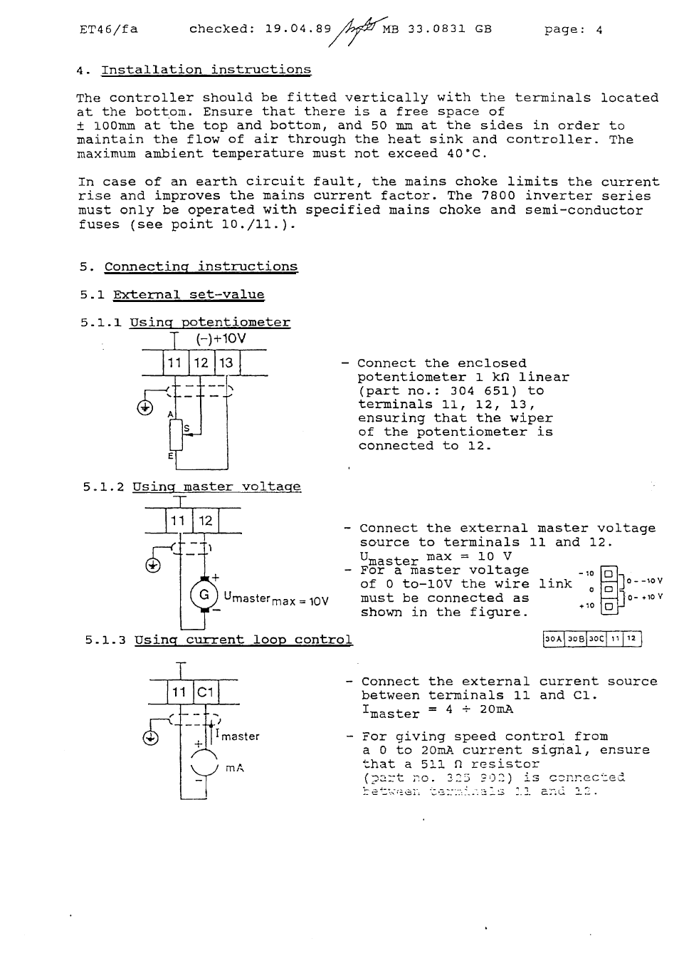
5..l.1
Usinc~ potentioxneter
(-)
+10V
—
Corrnect the enclosed
potentiometer 1 kfl
linear
(part no..:
304
651)
to
terminals
11,
12,
13,
ensuring that the wiper
of
the potentiometer
is
connected
to
l2~
5.1.2
—
Connect the external master voltage
source to terminals
11
and 12.
Umaster max
=
10
V
—
For
a
master
voltage
of
0 to—lOV the wire
link
~
UmastermaxiOV
must be
connected
as
shown
in
the
figure.
5..l..3
Usinq~ current
loop
control
~f~B3Ocf12
—
Connect
the
external
current
source
between terminals
11
and Cl.
‚master
=
4
~-
20mA
-
For giving speed
control
froln
a 0 to
2OmA current
signal,
ensure
that
a 511 fl
resistor
(‚-x=~t ;o.
225
?D2)
is
c~nm-.ccted
—
-~
—.
master