Lenze TC Series dynamic brake with external resistors User Manual
Installation and operation instructions, Scd & scf series drives, Scl & scm series drives
Lenze Americas • 630 Douglas Street • Uxbridge MA 01569 • USA
Sales (800) 217-9100 • Service (508) 278 9100 • www.lenzeamericas.com
DG01C
13360068
SC & TC SERIES DYNAMIC BRAKING OPTION (For Use with External Resistors)
INSTALLATION AND OPERATION INSTRUCTIONS
(These instructions apply to Dynamic Braking modules 845-200, 845-400, and 845-500 ONLY)
The SC & TC Series Dynamic Braking option can be used with all SCD, SCL, SCM, and TCF models, and SCF models
with parameter version 306 or higher. The parameter version is displayed momentarily when power is applied, and also
appears on a label on the heatsink (For example: PV312).
SCD & SCF SERIES DRIVES
PROGRAMMING:
1. Set Parameter 09 (TB-31 OUTPUT) to DYNAMIC BRAKING (04).
WIRING:
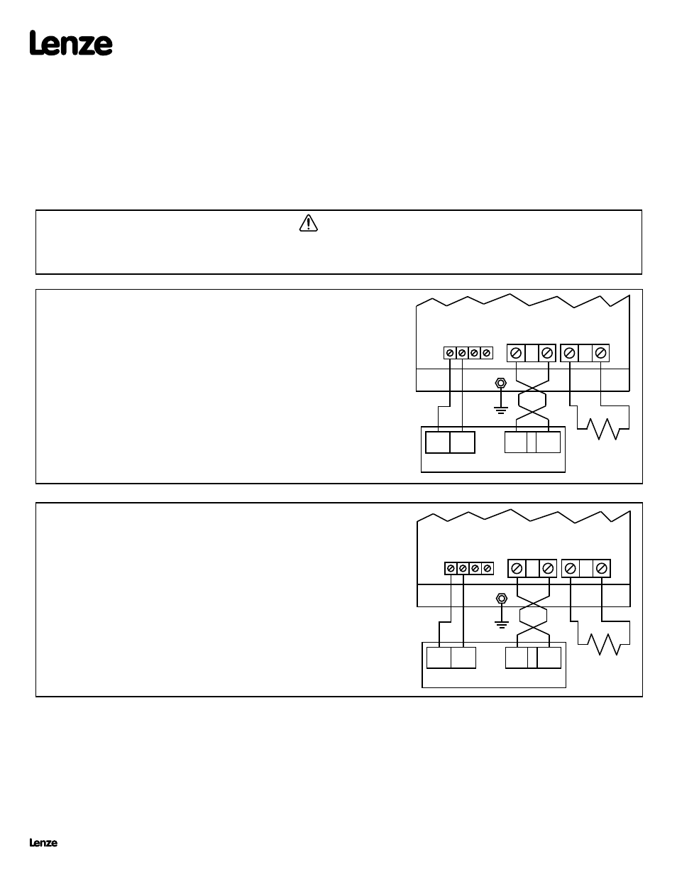
The diagram to the right illustrates how the DB module is wired to the SCD &
SCF Series drive.
See important wiring NOTES below.
NOTE 1: Use 18 AWG wire for control connections. Tighten DB module and drive control terminals to a torque of 2 lb-in
(0.2 Nm). Overtorque of terminals can result in damage.
NOTE 2: Use minimum 14 AWG wire for connections to B+, B-, R+, and R-. Tighten the DB module terminals to a torque
of 2 lb-in (0.2 Nm), and tighten the drive terminals to 4.5 lb-in (0.5 Nm). The B+ and B- wires MUST be twisted
together and must be less than 12 inches long. Twisting the R+ and R- wires is also recommended.
NOTE 3: External resistors (see selection chart on next page) are required when using Dynamic Braking modules 845-
200, 845-400, and 845-500. Only AC Tech supplied resistors are approved for use with 845 dynamic braking
modules.
EXTERNAL
RESISTORS
(SEE NOTE 3)
42
46
47
43
DB OPTION MODULE
31
2
GND
B -
B + R +
R -
B -
B +
SCD / SCF DRIVE
EXTERNAL
RESISTORS
(SEE NOTE 3)
42
46
47
43
DB OPTION MODULE
2
GND
B -
B + R +
R -
B -
B +
SCL / SCM DRIVE
13E
WARNING!
Remove power from the drive and wait three minutes before wiring the DB module. Incorrect wiring of the B+ and B- terminals
will result in equipment
damage! The B+ terminal on the DB module must be connected to the B+ terminal on the drive, and the B- terminal on the DB module must be connected
to the B- terminal on the drive.
SCL & SCM SERIES DRIVES
PROGRAMMING
1. Set Parameter 12 (TB-13E FUNCTION) to DYNAMIC BRAKING (20).
WIRING
The diagram to the right illustrates how the DB module is wired to the SCL
and SCM Series drive.
See important wiring NOTES below.
(13360068)