Coding by setting the dip switches, Preliminary works – Lenze EMF2174IB User Manual
Page 10
Preliminary works
Coding by setting the DIP switches
EDK2174DB DE/EN/FR 3.0
10
H2WichtHinw-Codierung_DIP_en
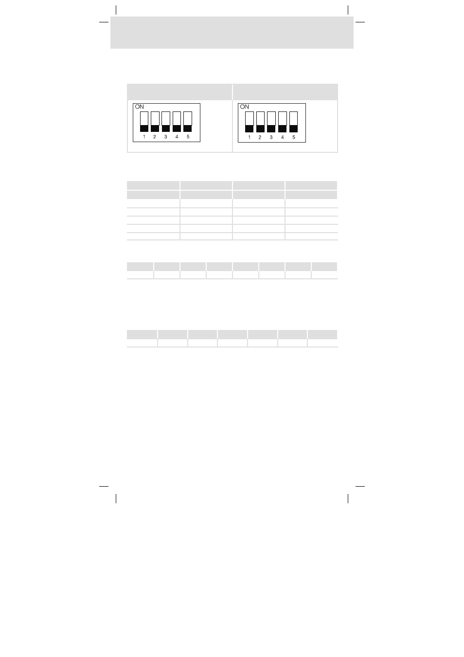
Coding by setting the DIP switches
Remove the front plate of the CAN addressing module in order to set the baud rate and the
controller address in its interior with DIP switches.
Left DIP switch
(S1L, S2L, S3L, S4L, S5L)
Right DIP switch
(S1R, S2R, S3R, S4R, S5R)
2174CAN005
Setting the baud rate
SetthebaudratewiththeswitchesS1L,S2LandS3L. Theswitchsettingsrequiredforsetting
the baud rate are represented in the following table:
Baud rate
S1L
S2L
S3L
[kbaud]
500
OFF
OFF
OFF
250
ON
OFF
OFF
125
OFF
ON
OFF
50
ON
ON
OFF
1000
OFF
OFF
ON
Setting the controller address
The switches S4L and S5L as well as the switches S1R to S4R correspond to certain values:
S4L
S5L
S1R
S2R
S3R
S4R
S5R
Value
1
2
4
8
16
32
-
In order to set the controller address, add up the values in a way that their sum equals the
controller address. Then set those switches to ”ON” whose values you have added up.
Example:
Setting the controller address 27
The sum of the values has to equal 27: 1 + 2 + 8 + 16 = 27
Ö
Switch setting:
S4L
S5L
S1R
S2R
S3R
S4R
S5R
ON
ON
OFF
ON
ON
OFF
-
Having set baud rate and controller address, fasten the front plate to the CAN addressing
module.