5 communication time, 1 cycle time, 2 processing time 8200 vector / 8200 motec – Lenze E82ZAFIC010 User Manual
Page 16: Communication time, Cycle time, Processing time 8200 vector / 8200 motec, Technical data
Technical data
Communication time
Cycle time
l
16
EDS82ZAFIC EN 2.0
4.5
Communication time
4.5.1
Cycle time
The cycle time of the communication system is the time required to exchange all process
data between the INTERBUS master and the nodes.
It depends on the data of the communication system and can be calculated e. g. for a baud
rate of 500 kbps as follows:
t
zykl
+ 3.35 @ 10
*3
(n ) 48 ) 3 BK) ) 0.24 L ) 0.2
t
cycl
Cycle time [ms]
n
Sum of all data bits in the INTERBUS ring
BT
Number of bus terminals
L
Length of the remote bus cable [km]
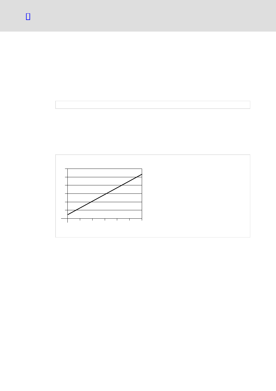
The following diagram shows the relationship between the cycle time and the number of
connected bus nodes. The given values refer to the connection of Lenze controllers
(e. g. 82xx) with 48 bits (1 parameter data word + 2 process data words.
12
10
8
6
4
2
10
20
30
40
50
60
Cycle time
[ms]
Number of bus nodes
1
Fig. 4−1
Relationship between cycle time and number of bus nodes
4.5.2
Processing time 8200 vector / 8200 motec
The processing time in the controller is added to the INTERBUS transmission time or cycle
time.
There are no dependencies between parameter data and process data.
ƒ
Parameter data (PCP): approx. 30 ms + 20 ms tolerance
ƒ
Process data (PCD): approx. 3 ms + 2 ms tolerance