2 adjustment of output speed, Adjustment of output speed, Maintenance – Lenze SIMPLABELT Compact Units User Manual
Page 21
Maintenance
21
L
BA S’belt KE EN 1.0
Disassembly with Z-design (see Fig. 2):
1. Activate the drive and accelerate it to max. speed, then switch off the drive and disconnect it
from the mains.
2. Loosen 6 screws (1.16; 1.15). Then push aside the covers (5BA and 4BA) to remove the V-belt
(3BA) from the variable speed pulley (1BA). The three-phase AC motor (5.0) must be
supported.
Assembly (U-design and Z-design)
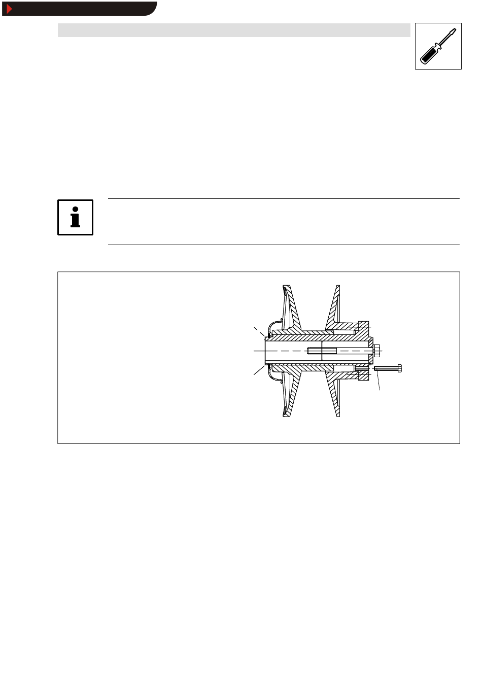
Note!
With sizes 31 and 40, the spring-loaded variable speed pulley can be opened by screwing a screw
into the flange (Fig. 7).
Remove the screw after assembly!
K11.0265
only with sizes 31 and 40
Required screw dimensions
Size 31: M6 x 40 (DIN933)
Size 40: M12 x 45 (DIN933)
Fig. 7
Variable speed pulley
1. First place the new V-belt onto the mechanically adjustable variable speed pulley (1BA) and
then draw it over the spring-loaded variable speed pulley (2BA) (see Fig. 1 and Fig. 2).
2. Refix housing (6 screws).
3. Start test running and check the speed limitating and the adjustment of the speed indicators
by means of a hand tacho. A readjustment may be necessary (see chap. 6.2.2).
6.2.2
Adjustment of output speed
The limit for the output speeds n
2min
and n
2max
are factory-set. A readjustment according to the
indication on the nameplate (pos. 1) may be necessary in the event of increased wear or after the
change of the V-belt (Fig. 1 and Fig. 2).
Show/Hide Bookmarks