Trailer hitch for gl 1800, Installation – Kuryakyn 7641 TRAILER HITCH FOR GL1800 User Manual
Page 4
PAGE
4
STEP 13
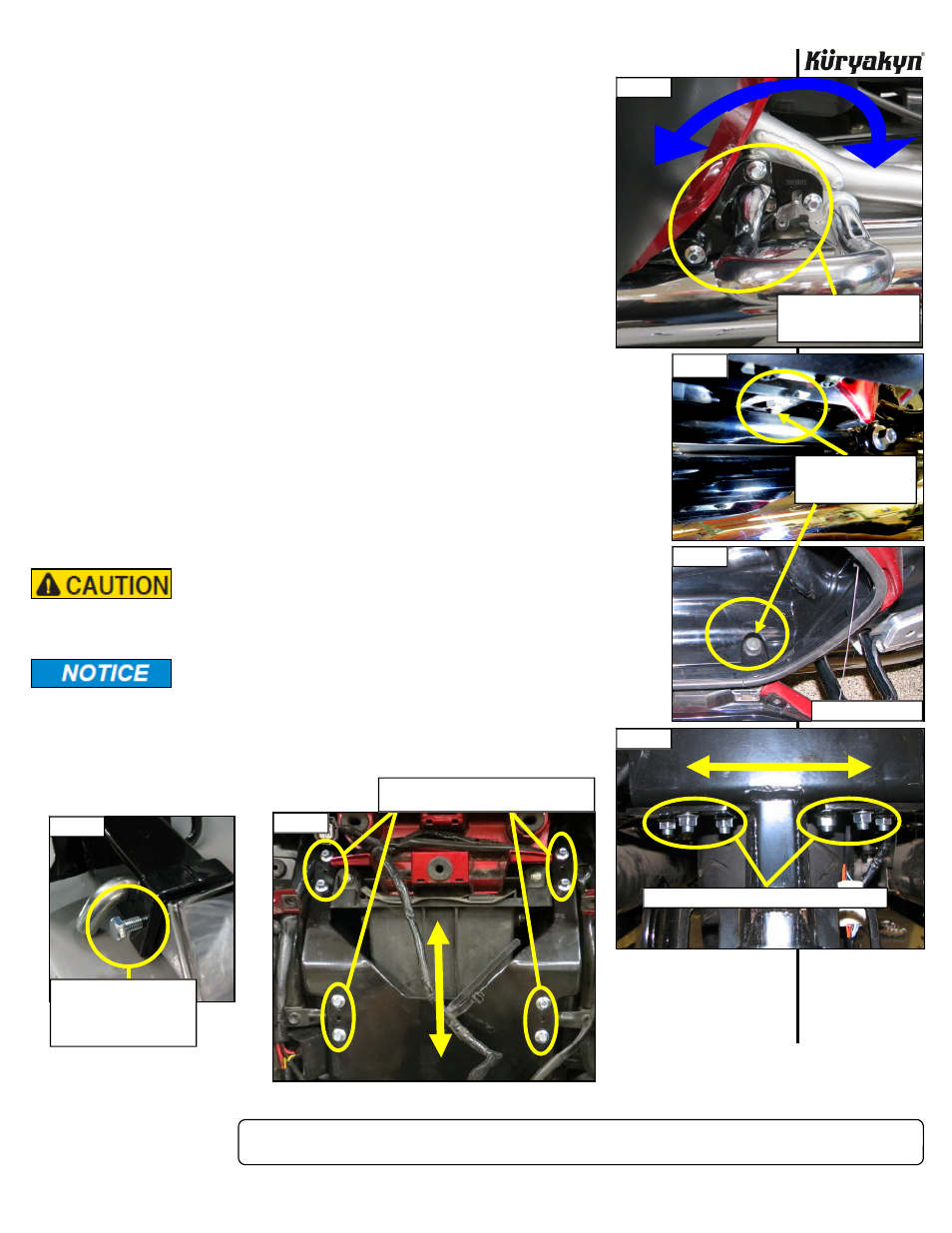
Install the drawbar into the receiver assembly. Secure with the hitch pin
and hair pin clip. Install the included M6-1.0 X 10mm hex head cap screw
in the threaded hole in the receiver (PIC 16) and tighten securely. This is
to help keep the drawbar from rattling when no weight is attached to the
hitch. Install the ball on the receiver.
NOTE:
To use the included receiver plug: remove the hair pin clip, hitch
pin, drawbar and the M6 hex head cap screw from Step 13. Insert
the receiver plug into the receiver and secure with the hitch pin
and hair pin clip. When the receiver plug is installed, the M6 hex
head cap screw (PIC 16) CAN NOT be used, stow this with the
drawbar.
STEP 14
Reinstall the floorboard covers, floorboard-Tighten to 20 FT/LBS, and
side covers to the motorcycle.
STEP 15
Re-install the rear turn signal housing and rear panel.
STEP 16
Check for clearance between any component on the motorcycle and the
stabilizer bars from the front mounting point to the rear mounting point.
Readjust per Steps 11-13 until clearance is achieved.
Ensure that the installation of this product does not interfere
with the proper operation of the motorcycle before riding.
It is the installer’s responsibility to ensure that all of the fasteners
(including pre-assembled) are tightened before operation of the
motorcycle. Küryakyn will not provide warranty coverage on products
or components lost due to improper installation or lack of
maintenance. Periodic inspection and maintenance are
required on all fasteners.
TRAILER HITCH for GL 1800
INSTALLATION
PIC 16
USE M6-1.0 X 10mm HERE
STOW WITH DRAWBAR
IF RECEIVER PLUG IS
USED
PIC 14
LOOSEN THESE FOR SIDE TO SIDE ADJUSTMENT
PIC 11
LOOSEN THESE FOR FRONT
OF SADDLEBAG AND
EXHAUST CLEARANCE
-cont.-
PIC 15
LOOSEN THESE FOR REAR OF SADDLEBAG
AND EXHAUST CLEARANCE
PIC 13
CHECK THIS FASTENER
FOR STABILIZER BAR
CLEARANCE
PIC 12
RIGHT SIDE SHOWN