Trailer hitch for gl 1800, Installation – Kuryakyn 7641 TRAILER HITCH FOR GL1800 User Manual
Page 3
PAGE
3
STEP 5
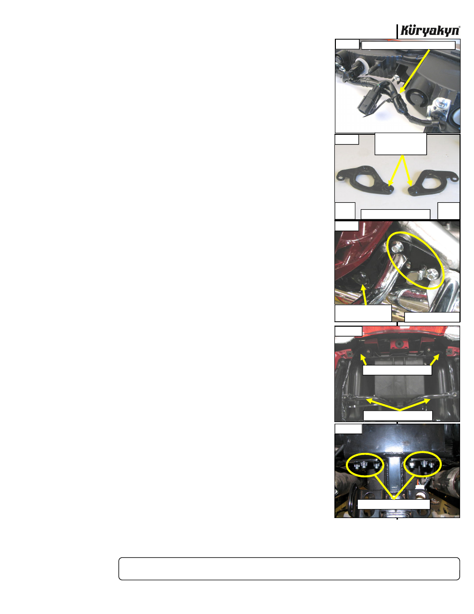
Remove the connector from the mount on the left side of the turn signal housing (PIC 5) and
secure it to the main turn signal harness with the included cable tie. PIC 6 Remove
the mount from the turn signal housing. Set the mount aside, it will not be reused.
STEP 6
Determine the left from the right (sitting on bike) stabilizer bar bracket. PIC 7
STEP 7
Install the right stabilizer bar mount to the motorcycle by inserting the rear leg of
the guard (removed in Step 3) through the opening in the mount. PIC 8 The rear
guard will go between the stabilizer bar mount and the motorcycle frame. Loosely
fasten the mount and guard to the motorcycle using two of the M8-1.25 X 25mm
flange head cap screws and M8 external tooth lock washers. Repeat for the left
stabilizer
bar
mount.
STEP 8
From the rear of the bike, slide the stabilizer bars up to the mounts. They will
locate just above the inside of the top of the mufflers. Using two of the supplied
M8 external tooth lock washers and M8-1.25 X 25mm flange head cap screws,
loosely attach the stabilizer bars to the stabilizer bar mounts installed in Step 7.
STEP 9
Place the frame clamps on the sub-frame support bars. Note that there are two
different diameter clamps. PIC 9 The larger diameter clamps are used on the
upper frame bar, and the smaller diameter clamps are used on the lower frame
bar. PIC 9 Once the clamps are in position on the frame bars, set the trailer hitch
receiver plate into place. Loosely attach the plate to the clamps with the included
M6-1.0 X 20mm flange screws and M6 external tooth lock washers.
STEP 10
Using the M10-1.25 X 25mm flange head cap screws, M10 nuts and M10 external
tooth lock washers loosely attach the stabilizer bars to the bottom side of the
trailer hitch receiver plate. PIC 10 The flange head cap screws drop in through the
receiver, through the stabilizer bars, then are secured with the external tooth lock
washer first, then the hex nut.
STEP 11
Check for clearance between the front saddlebag bolt and the stabilizer bars. The
stabilizer bar mount can be rotated as in PIC 11 to gain clearance. If enough
clearance on the saddlebag fastener (PIC 12) cannot be obtained by this then
remove the bolt (PIC 13) and install the included flat washer, then the included
lock washer on the bolt and re-install it. Tighten securely. Tighten the stabilizer
bar mount to receiver plate fasteners securely. Leave the stabilizer bar fastener to
front
stabilizer
mount loose for now.
STEP 12
Check for clearance between the rear exhaust mounting point and the rear of the
stabilizer bars. The bars can be moved in or out (PIC 14) for side to side
clearance. The receiver plate can be moved up or down (PIC 15) for clearance.
Once sufficient clearance has been achieved, tighten the six M10 fasteners on the
stabilizer bar/receiver plate securely. Next tighten the eight M5 fasteners on the
receiver
plate/bar
clamps
securely.
Last, tighten the front stabilizer bar fasteners
from Step 11 securely.
TRAILER HITCH for GL 1800
INSTALLATION
-cont.-
PIC 6
SECURE CONNECTOR TO HARNESS
PIC 10
USE M10 HARDWARE HERE
PIC 9
USE LARGE CLAMPS HERE
USE SMALL CLAMPS HERE
PIC 7
LEFT
SIDE
RIGHT
SIDE
RAISED THREADED
BOSS FACES OUT
AND TO THE REAR
PIC 8
STABILIZER BAR MOUNTS
RIGHT SIDE SHOWN
ATTACH STABILIZER
BAR HERE